Eugenio,77
mail@toyota-club.net
© Toyota-Club.Net
Jul-Dec 2010
Production of automatic transmissions for Toyota 4WD models with a center differential locking control by hydro-mechanical clutch started in 1988. Concerned version - AT A241H - was installed until 2002 in various models of Corolla family (E90, E100, E110 generations).
1. Overview
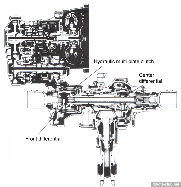
AT A241H is based on the transmission A240L (hydraulic control). Center differential locking - by hydraulic multi-plate clutch. Center differential gears - bevel.
Operation modes: basic - "AUTO", during towing or spare wheel installed - "OFF". Service locking modes: basic - "FREE"; at service - "FREE" or "LOCK", lock control switch - "OFF"
Fluid (AT and center differential locking) - Toyota ATF Type T (08886-00405). Transfer oil - Toyota transaxle oil E50 (08885-80206).
Center differential locking control is performed in "AUTO" mode. When the selector is in position "D" and "2", system provides a minimum differential limit force, that reduces resistance when driving at low speeds and maneuvering; when the selector is in position "L" and "R", system provides maximal limit force to improve off-road possibilities.
Extraction from Japanese owner manual - see here
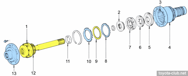
2. Construction
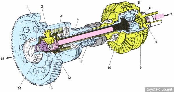
Center differential and transfer. 1 - front differential pinion gear, 2 - front differential pinion gear shaft, 3 - front differential right side gear, 4 - intermediate shaft, 5 - center differential pinion gear, 6 - center differential right side gear, 7 - to front right driveshaft, 8 - spline, 9 - transfer drive gear case, 10 - center differential left side gear, 11 - front differential right case, 12 - front differential left case, 13 - main gear case, 14 - front differential left side gear, 15 - to front left driveshaft.
1. Control switch in "AUTO", straight driving.
The power is transmitted from the transmission via main gear to the main gear case, then via splines to the front differential case. Here the power via the pinion gears split evenly between left and right side gears, which turn at the same speed as the center differential case (pinion gears do not rotate). The power from the left side gear is transmitted to the front differential case. Here, as in the center differential, the power split evenly between the left and right side gears and is further transmitted to the right and left driveshafts and wheels. The power from the right side gear of center differential, through the transfer gears and propeller shaft is transmitted to the rear differential.
2. Control switch in "AUTO", there is a difference between the speed of the front and rear wheels.
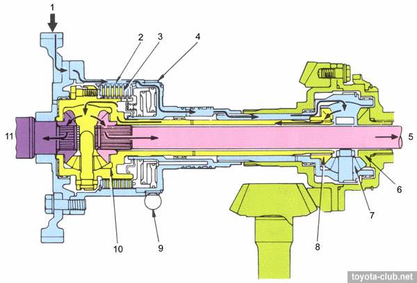
When speed difference arises between the front and rear wheels, the center differential operates, whereby the speed difference arises between main gear case and the front differential case. To reduce this difference the fluid pressure is applied to the pistons of hydraulic multi-clutch to compress the clutch pack. The frictional force depends on the driving conditions (throttle opening angle, vehicle speed, selector position) and is selected to provide optimum torque at the front and rear wheels.
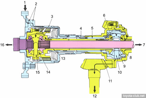 |
"Auto" mode, the difference between the speed of the front and rear wheels. 1 - from AT, 2 - main gear mounting, 3 - hydraulic multi-plate clutch, 4 - splines, 5 - center differential case, 6 - center differential left side gear, 7 - to front right driveshaft, 8 - center differential right side gear, 9 - center differential pinion gear, 10 - center differential pinion gear shaft, 11 - transfer drive and driven gear, 12 - to rear differential, 13 - front differential case, 14 - front differential pinion gear, 15 - front differential pinion gear shaft, 16 - to front left driveshaft.
3. Control switch in "OFF", service maintenance / testing of brake system.
In this mode the solenoid valve is off and the pressure does not supplied to to the clutch pack. And, if the front or rear wheels rotate, while the other are stopped, speedometer indicates half of the wheel speed. For example, if the rear wheels are stopped, power is transmitted to the pinion gears via main gear case and center differential case, but since right side gear does not turn the center differential pinion gears rotate around its axis while moving around the right drive gear. Speed of front differential case is sum of these two rotation speeds, so it rotates twice as faster than the center differential. Speedometer drive gear is fitted to main gear case and rotates at the speed of center differential case.
"OFF" mode, service maintenance. 1 - from AT, 2 - main gear mounting, 3 - hydraulic multi-plate clutch, 4 - speedometer drive gear5 - to front right driveshaft, 6 - center differential right side gear, 7 - center differential pinion gear, 8 - center differential left side gear, 9 - speedometer driven gear, 10 - front differential case, 11 - to front left driveshaft.
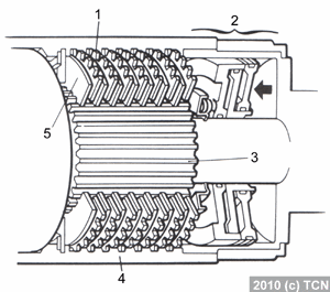
3. Hydraulic multi-plate clutch
Clutch [1]. 1 - front differential, 2 - piston return spring, 3 - spline, 4 - main gear right case, 5 - piston 2, 6 - piston reaction sleeve, 7 - piston 1, 8 - clutch plate, 9 - clutch disc, 10 - flange, 11 - front differential case thrust washer, 12 - spline, 13 - main gear left case.
| The clutch is installed between main gear case and front differential case, consists of a set of discs and plate, two pistons and other components. |
Clutch [2]. 1 - clutch plate, 2 - piston 1 & 2, 3 - front differential case, 4 - main gear case, 5 - clutch disc.
|
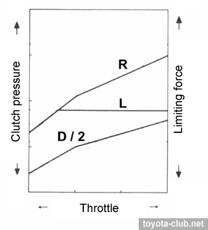
The control system limits the operation of the center differential, by creating friction between the clutch discs and plates when it compressed with moving pistons 1 and 2. The inner splines of clutch discs mesh with splines of the front differential case, the outer splines of clutch plates mesh with splines of inner surface of the main gear housing. Hydraulic pressure is regulated by transmission valve block in accordance with throttle position, vehicle speed and selector position.
| The relationship between throttle position and differential limiting force |
| Range | Throttle opening angle | Limiting force |
| D & 2 | small | small |
| D & 2 | large | large |
| D & 2 | speed above 100 km/h | no |
| L | small and large | large |
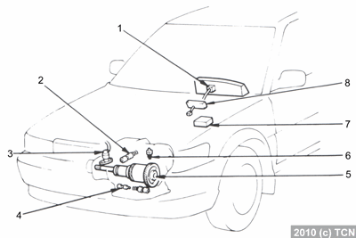
4. Control system
Control system. 1 - speed sensor, 2 - clutch control valve, 3 - solenoid valve, 4 - pressure regulator valve, 5 - hydraulic multi-plate clutch, 6 - hydraulic pressure switch, 7 - center differential ECU, 8 - center differential control switch.
| Functions of components |
| 1. Speed sensor | Detects and converts the vehicle speed to electrical signal and transmits it to the control unit |
| 2. Clutch control valve | Applies or cuts off pressure to the pistons of clutch |
| 3. Solenoid valve | Applies or cuts off pressure to the control valve |
| 4. Pressure regulator valve 2 | Modulates hydraulic pressure or transmits line pressure via control valve to clutch pistons |
| 5. Hydraulic multi-plate clutch | Limits center differential operation |
| 6. Hydraulic pressure switch | Determines 4th gear position and transmits a signal to the control unit |
7. Control unit
| Sends or cuts off current to the solenoid valve on the basis of signals from the speed sensor, pressure switch and control switch
|
| 8. Center differential control switch | Switches differential control modes ("AUTO" and "OFF") |
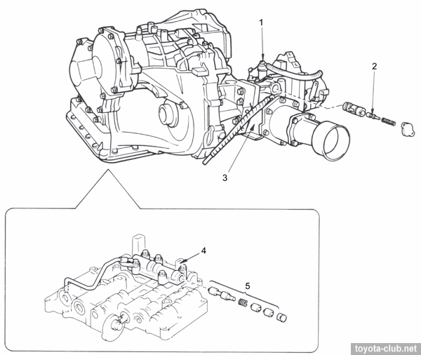
5. Hydraulic system
Control system [2]. 1 - solenoid valve, 2 - clutch control valve, 3 - transfer left case, 4 - upper valve body, 5 - pressure regulator valve 2.
Pressure regulator valve 2 is installed in the upper valve body, control valve and solenoid valve - in the transfer left case. The other components of the hydraulic system are located and operate similarly to the automatic transmission A240L.
System operation
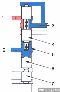
1. Control switch "OFF", selector position "D" or "2"
The solenoid valve is off. The pressure acts on the top of control valve and pushes it downwards, compressing the return spring. Thus, the pressure from the pistons 1 and 2 is released, the center differential becomes free.
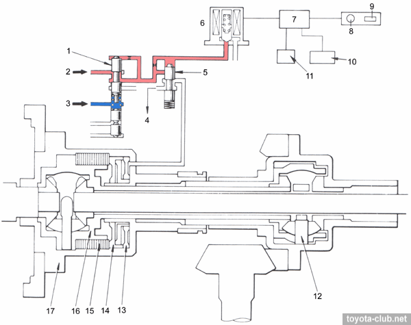
"OFF" mode, "D" or "2" range. 1 - pressure regulator valve 2, 2 - line pressure, 3 - throttle modulator pressure, 4 - drain, 5 - clutch control valve, 6 - solenoid valve (OFF(, 7 - ECU, 8 - center differential indicator light (OFF), 9 - center differential control switch (OFF), 10 - speed sensor, 11 - hydraulic pressure switch, 12 - center differential, 13 - piston 2, 14 - piston 1, 15 - multi-plate clutch, 16 - front differential case, 17 - main gear case.
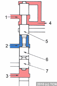
2. Control switch "AUTO", selector position "D" or "2"
The solenoid valve is on. Pressure does not act on the top of control valve and it is pushed upwards by return spring. Thus, pressure from the pressure regulator valve 2 is transmitted via control valve to pistons 1 and 2, the pistons move and compress the clutch pack, and this limiting differential operation.
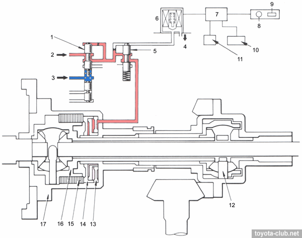
"AUTO" mode, "D" or "2" range. 1 - pressure regulator valve 2, 2 - line pressure, 3 - throttle modulator pressure, 4 - drain, 5 - clutch control valve, 6 - solenoid valve (ON), 7 - ECU, 8 - center differential indicator light (ON), 9 - center differential control switch (AUTO), 10- speed sensor, 11 - hydraulic pressure switch, 12 - center differential, 13 - piston 2, 14 - piston 1, 15 - multi-plate clutch, 16 - front differential case, 17 - main gear case.
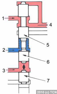
Operation of the pressure regulator valve 2
"D" or "2" range Pressure regulator 2 by using throttle modulator pressure modulates line pressure into control pressure and directs it to control valve. Plungers 1 and 2 remain pushed down by throttle modulator pressure and spring force.
|
1 - line pressure (from primary regulator valve), 2 - throttle modulator pressure, 3 - differential control pressure, 4 - pressure regulator valve 2, 5 - spring, 6 - plunger 1, 7 - plunger 2.
|
"R" range Line pressure acts on the bottom of plunger 2, and both the plunger and the spool rise, and the channel from the primary regulator valve to control valve is opened. Line pressure from the primary regulator valve does not adjust by regulator valve 2.
|
1 - line pressure (from primary regulator valve), 2 - throttle modulator pressure, 3 - line pressure (from manual valve), 4 - line pressure, 5 - pressure regulator valve 2, 6 - plunger 1, 7 - plunger 2.
|
"L" range Line pressure acts on the bottom of plunger 1, and the plunger 1 and the spool rise, and the channel from the primary regulator valve to control valve is opened. Line pressure from the primary regulator valve does not adjust by regulator valve 2.
|
1 - line pressure (from primary regulator valve), 2 - throttle modulator pressure, 3 - line pressure (from manual valve), 4 - line pressure, 5 - pressure regulator valve 2, 6 - plunger 1, 7 - plunger 2.
|
6. Service locking
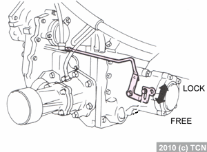
Service mechanical locking of center differential was used on early models (E90 until 1995, E100 until 1994). This mechanism is used for certain types of inspections and adjustments, such as braking force check using a dynamometer with locked front or rear wheels. Service lock control lever is mounted on the transfer case.
Caution. Do not change the position of the lever except for the purpose of inspection and adjustment. To prevent damage of the transmission, driving with the lever in the "LOCK" position is prohibited.
There are two posotions of service lock:
"FREE" - normal automatic locking.
"LOCK" - center differential is mechanically locked, power is equally splitted between front and rear wheels.
When using the service lock should observe the following rules.
1. If the lever does not move smoothly, it is necessary to switch it while rotating the front wheel, but without applying excessive force.
2. Locking bolt must be tighten only with lever switched fully to one of positions.
3. After inspection the lever must be switched in "FREE".
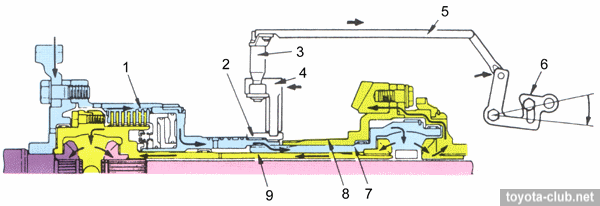
Service lock operation
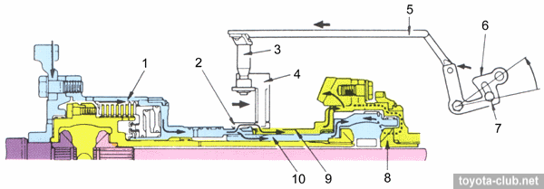
When "LOCK" mode is activated (turn anti-clockwise) the rod connected to the lever moves to the left and turns the shift fork shaft. The fork moves locking sleeve to the right and locks the center differential. The splines on the sleeve inner surface mesh with splines on the transfer drive gear case, whereby the right side gear if center differential is locked to the center differential case.
Service lock (LOCK). 1 - main gear case, 2 - center differential locking sleeve, 3 - shift fork shaft, 4 - shift fork, 5 - rod, 6 - select lever, 7 - locking bolt, 8 - center differential right side gear, 9 - transfer drive gear case, 10 - center differential case.
At "FREE" mode (turn clockwise) the rod moves to the right and rotates the fork shaft, the fork moves sleeve to the left and center differential is released.
Service lock (FREE). 1 - main gear case, 2 - center differential locking sleeve, 3 - shift fork shaft, 4 - shift fork, 5 - rod, 6 - select lever, 7 - center differential right side gear, 8 - transfer drive gear case, 9 - center differential case.
7. Additions
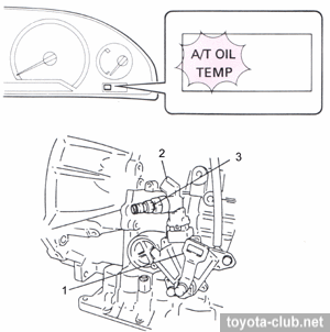
| Some models was equipped with ATF temperature sensor and ATF overheat indicator light in the instrument panel. If ATF temperature is over 145±3 degrees, the switch is activated and the indicator lights up, then when temperature becomes below 138 degrees light goes off. |
1 - neutral start switch, 2 - to oil cooler, 3 - fluid temperature switch.
|
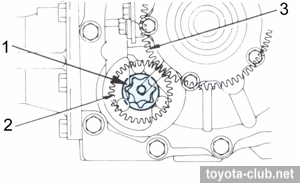
| The various transmission components use different types of lubrication: transmission, center and front differentials - ATF, transfer case - transmission oil (supplied by a separate pump). Trochoid type oil pump is mounted on a support of transfer drive gear. |
1 - oil pump, 2 - driven gear, 3 - drive gear.
|
Toyota all-wheel drive. Review
·
ATC/DTC ·
V-Flex ·
DTV ·
i-Four ·
Torsen ·
E-Four ·
·
C.Diff Auto
A241H /
A540H ·
C.Diff Lock ·
C.Diff Visc ·
FT-Visc ·