|
Eugenio,77
mail@toyota-club.net
© Toyota-Club.Net
Sep 2019 - Jun 2021
| Engine | Displacement, cm3 | Cylinder diameter x Piston stroke, mm | Compression ratio | Power, PS | Torque, Nm | RON | Model |
| V35A-FTS | 3444 | 85.5 x 100 | 10.5 | 421 / 6000 | 600 / 1600-4800 | 95 | type'17 |
| V35A-FTS | 3444 | 85.5 x 100 | 10.4 | 414 / 5200 | 650 / 2000-3600 | 95 | type'21 |
V35A-FTS (3.5 D-4ST DVVT-iE) - for RWD-based vehicles, combined fuel injection, turbocharger (twin-turbo), DVVT-iE or DVVT-i. Applications: Lexus LS (type'17); Toyota Land Cruiser 300, Tundra, Sequoia, Lexus LX600 (type'21).
It is the second engine of the "Dynamic Force" generation, the first in Toyota history turbocharged V-engine. Some of the technical solutions are similar to the new inline-4 A25 and M20 engines, the others look even more conservative.
Upd. Description of design differences for type'21 (LC 300) has been added.
Engine mechanical - Block
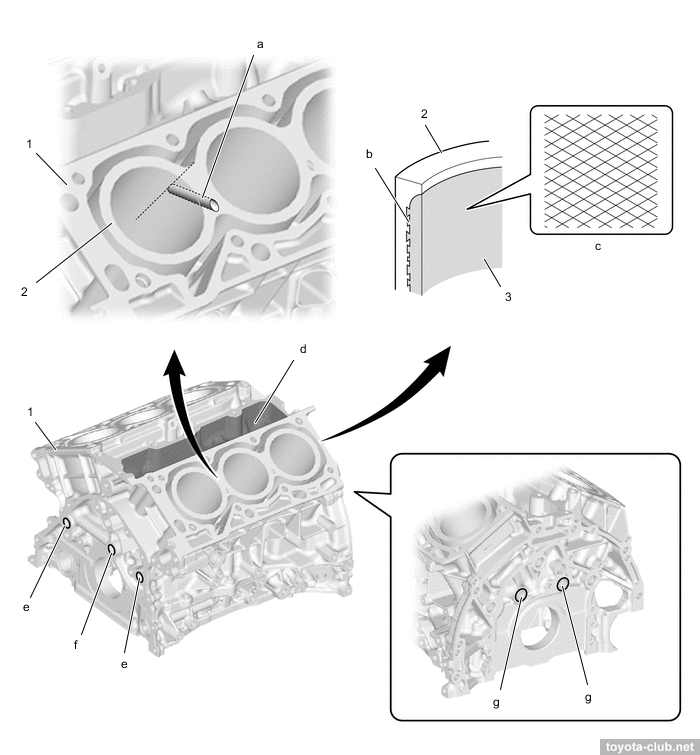
The cylinder block - aluminum "open deck" with thin cast iron liners. The liners are fused into block and their special rough outer surface promotes strong connection.
|
1 - cylinder block, 2 - cylinder bore, 3 - liner. a - drill passage, b - liner, c - bore cross hatch, d - PCV separator chamber, e - sub oil gallery, f - main oil gallery, g - air passage.
|
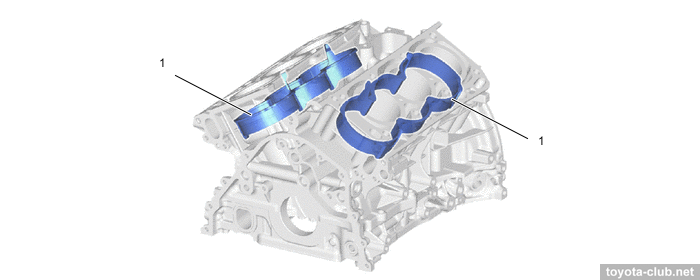
There are the spacers in the water jacket installed, it allows more intensive coolant circulation near the top of the cylinder, which improves heat dissipation and helps to more evenly thermally load.
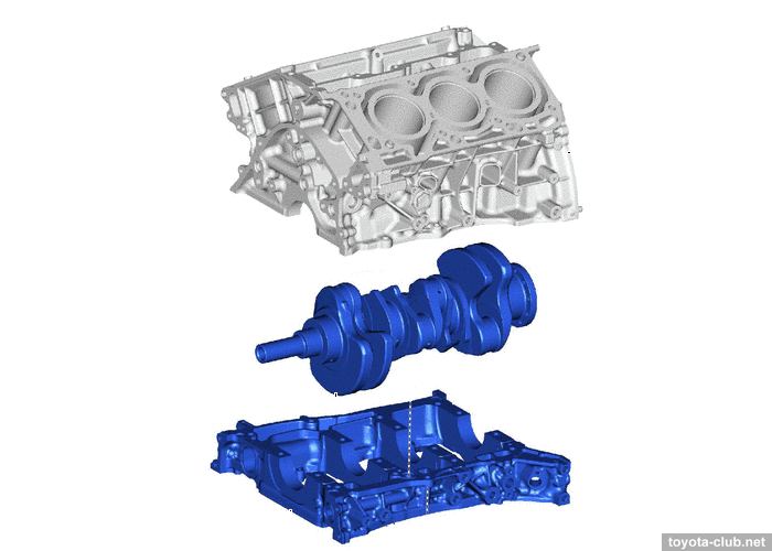
The massive alloy crankcase mounted to block is also a single crankshaft bed (similar to ZZ series), which provides the necessary rigidity to the structure.
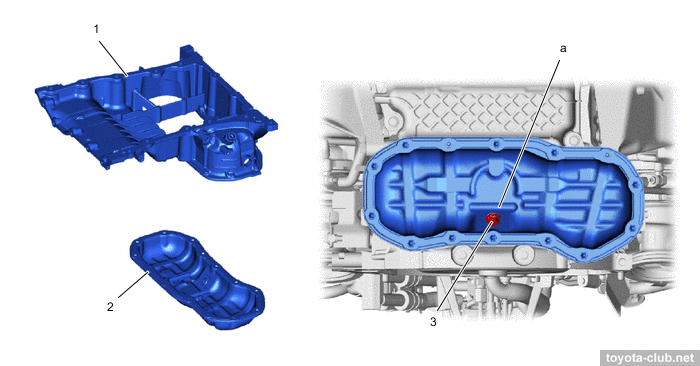
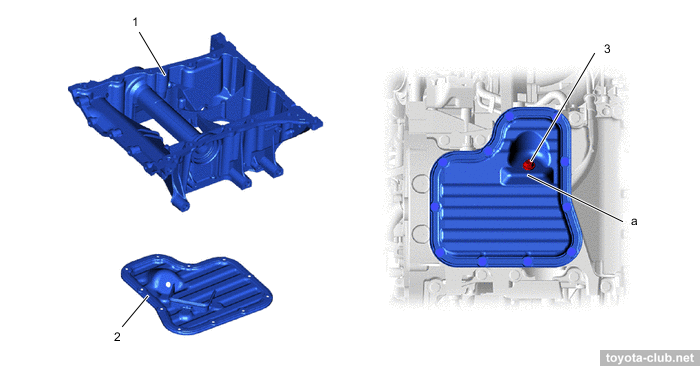
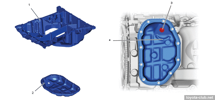
The upper part of the oil sump is cast, the lower part is steel-stamped (sump of 4WD version is more complicated).
|
Type'17 2WD. 1 - oil pan upper, 2 - oil pan lower, 3 - drain plug
|
|
Type'17 4WD. 1 - oil pan upper, 2 - oil pan lower, 3 - drain plug
|
|
Type'21. 1 - oil pan upper, 2 - oil pan lower, 3 - drain plug
|
The crankshaft has 5 balance weights, 4 narrow journals and integrated main bearing caps.
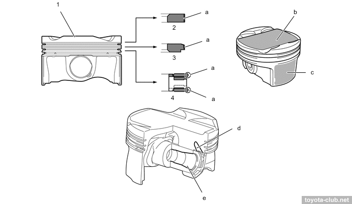
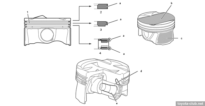
Pistons - aluminum, lightweight, with a friction reducing polymer coating. The edges of the compression rings and the oil scraper ring have an anti-wear PVD (Physical Vapor Deposition) coating. The pistons are connected to the rods with fully floating pins.
|
Type'17. 1 - piston, 2 - compression ring 1, 3 - compression ring 2, 4 - oil ring. a - PVD processing, b - tumble maintaining shape, c - resin coating, d - reduction, e - tapered piston inner diameter
|
|
Type'21. 1 - piston, 2 - compression ring 1, 3 - compression ring 2, 4 - oil ring. a - PVD processing, b - tumble maintaining shape, c - resin coating, d - reduction, e - tapered piston inner diameter
|
In accordance with the modern trends - the engine is "long-stroke", with a high average piston speed, so it is radically different from the previous V6 engine series.
Engine mechanical - Cylinder head
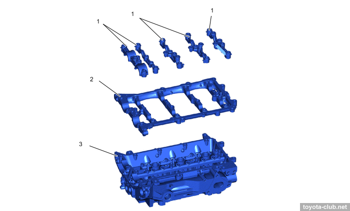
The camshafts are installed in a separate housings, which mounted on the cylinder heads - it simplifies the design and manufacturing technology of cylinder head, however, another joint of parts has appeared requiring sealing.
|
1 - camshaft bearing cap, 2 - camshaft housing LH, 3 - cylinder head LH
|
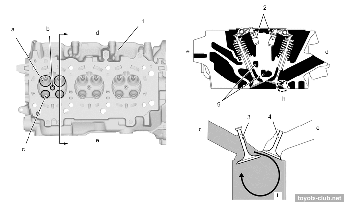
Instead of traditional press-fit, the intake valve seats made by the "laser spray" method are used (like another DF motors and old 1ZZ-FE engine). They are much thinner than usual, providing better cooling of the valves and optimization of the ports shape and size. The intake channel is "straight".
|
1 - cylinder head, 2 - valve lash adjuster, 3 - intake valve, 4 - exhaust valve. a - intake port, b - spark plug hole, c - exhaust port, d - intake side, e - exhaust side, g - water jacket, h - laser cladded valve seat, i - tumble flow
|
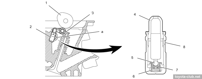
The angle between the intake and exhaust valves is 41°, very large for Toyota. The conical shape of the upper part of the valve spring allows to made the spring retainer smaller and light. Sodium cooling of the exhaust valves is implemented. There are valve adjusters and roller rockers in the valve mechanism.
|
1 - cam, 2 - valve lash adjuster, 3 - valve rocker arm, 4 - plunger, 5 - check ball, 6 - plunger spring, 7 - check ball spring, 8 - oil hole. a - oil passsage
|
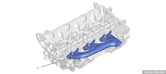
The exhaust manifold is integrated into the cylinder head for compactness and weight reduction.
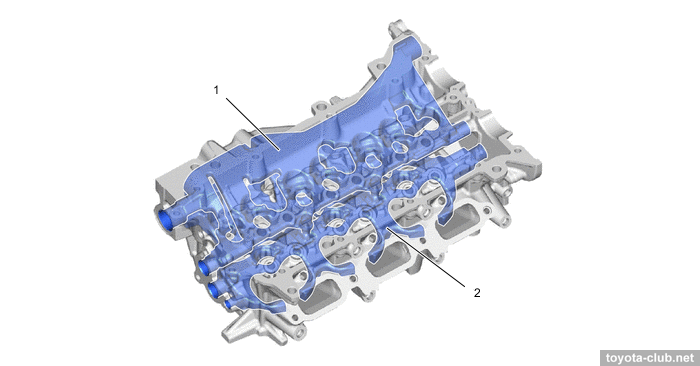
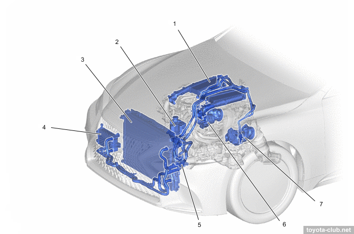
The water jacket in the head is divided into two levels. The volume of antifreeze concentrated in the lower part helps to cool the combustion chamber, minimizing the temperature spread across the cylinders. At the same time, the integrated exhaust manifold is also cooled, which reduces the temperature of the exhaust gases upstream the turbocharger.
|
1 - water jacket (upper), 2 - water jacket (lower)
|
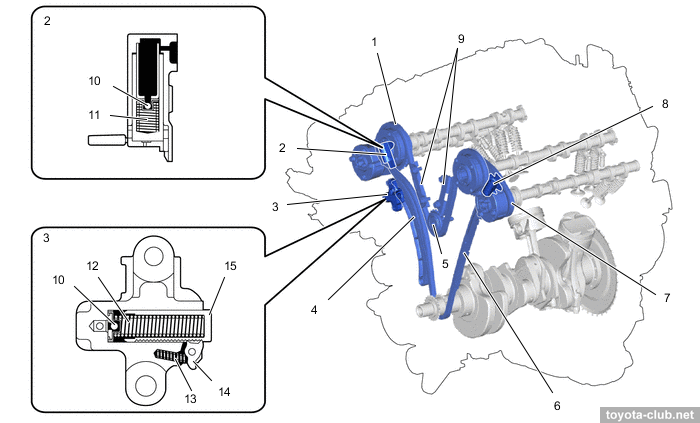
Timing drive is "two-step". From the crankshaft by the primary roller chain (pitch 8 mm) intake camshafts are driven, and two short secondary chains for exhaust camshafts drive are used. Primary circuit tensioner - with a ratchet mechanism, spring and return valve, secondary chain tensioner have not ratchet, but also is spring enforced. Intermediate gear - with anti-noise rubber inserts at the base of the teeth.
|
1 - secondary chain RH, 2 - secondary chain tensioner, 3 - primary chain tensioner, 4 - tensioner slipper, 5 - idle sprocket, 6 - primary chain vibration damper, 7 - secondary chain LH, 8 - secondary chain tensioner, 9 - secondary chain vibration damper, 10 - ball, 11 - main spring, 12 - spring, 13 - cam spring, 14 - cam, 15 - plunger
|
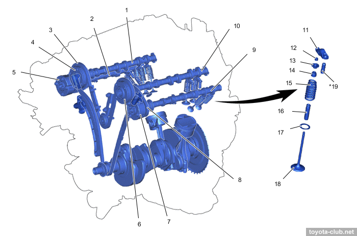
VVT actuators both on the inlet and outlet camshafts are installed (DVVT - Dual Variable Valve Timing).
Type'17: There are electrical variable valve timing mechanism for intake (VVT-iE) and traditional hydraulic for exhaust (VVT-i). Timing variations range - 85° for intake and 44° for exhaust. More about Toyota VVT operation.
Type'21: There are traditional hydraulic for intake and exhaust (VVT-i). Timing variations range - 65° for intake and 44° for exhaust. More about Toyota VVT operation.
|
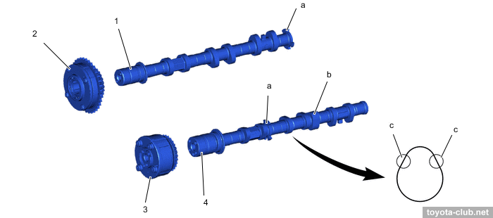
1 - intake camshaft RH, 2 - exhaust camshaft RH, 3 - chain 2 RH, 4 - timing gear intake RH, 5 - timing gear exhaust RH, 6 - timing gear intake LH, 7 - timing gear exhaust LH, 8 - chain 2 LH, 9 - exhaust camshaft LH, 10 - intake camshaft LH, 11 - valve rocker arm, 12 - valve stem cap, 13 - valve spring retainer, 14 - valve stem oil seal, 15 - valve compression spring, 16 - valve guide bush, 17 - valve spring seat, 18 - valve, 19 - valve lash adjuster
|
Each exhaust camshaft drives its own injection pump by a profiled cam, the right shaft also drives a vacuum pump.
|
1 - intake camshaft, 2 - timing gear intake, 3 - timing gear exhaust, 4 - exhaust camshaft. a - timing rotor, b - cam operating high-pressure fuel pump
|
The design of the vacuum pump is similar to ZR series, from which similar "features" should be expected.
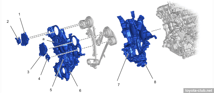
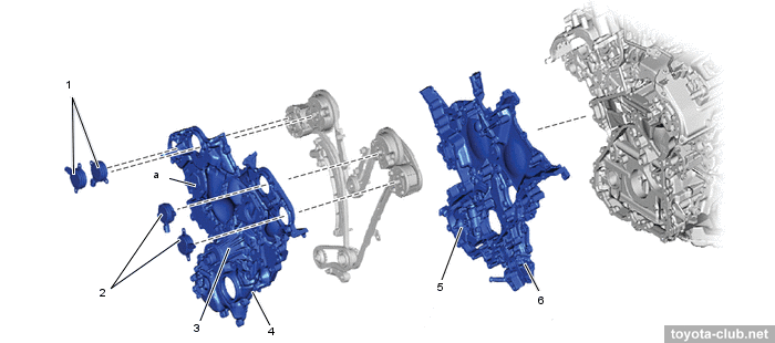
The timing chain is closed by two cast alloy covers. VVT-iE controllers and/or VVT-i valves are installed in the front cover, and the coolant pump is also built into it. The oil pump is integrated in the back cover.
|
Type'17. 1 - VVT-iE controller RH, 2 - VVT-i control solenoid RH, 3 - VVT-iE controller LH, 4 - VVT-i control solenoid LH, 5 - engine coolant pump, 6 - timing chain cover 1, 7 - oil pump, 8 - timing chain cover 2. a - service hole
|
|
Type'21. 1 - VVT-i solenoid (right), 2 - VVT-i (left), 3 - coolant pump, 4 - chain cover (front), 5 - oil pump, 6 - chain cover (rear). a - service hole
|
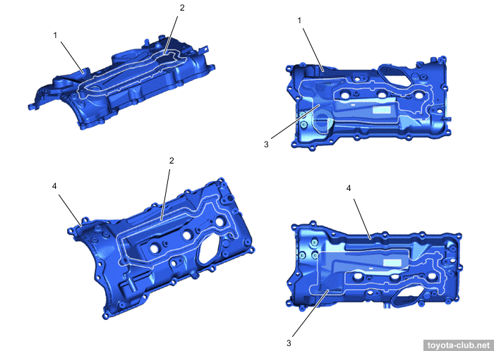
The cylinder head covers are polymer, with oil supply channel to rockers and oil separators.
|
1 - cylinder head cover RH, 2 - oil delivery pipe, 3 - baffle plate, 4 - cylinder head cover LH
|
Lubrication system
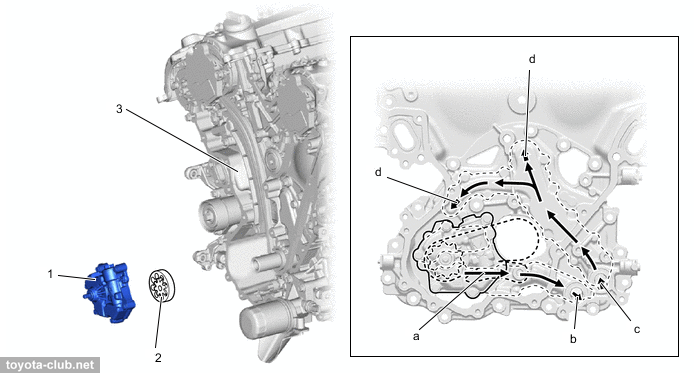
The oil pump is of a traditional design, with an internal bypass, integrated into the timing chain cover.
|
1 - timing chain cover, 2 - oil filter, 3 - oil strainer, 4 - oil pressure switching valve. a - piston lubrication oil passage
|
|
1 - oil pump cover, 2 - oil pump rotor, 3 - timing chain cover.
a - from oil pump, b - to oil filter, c - from oil filter, d - to cylinder block
|
For type'17 RWD a normal spin-on oil filter is used, mounted horizontally at the front side.
|
1 - oil filter, 2 - oil filter bracket
|
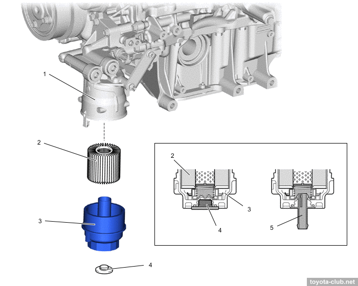
For type'17 4WD an "economical" filter with replaceable element is used.
|
1 - oil filter bracket, 2 - oil filter element, 3 - oil filter cap, 4 - oil filter drain plug, 5 - drain pipe
|
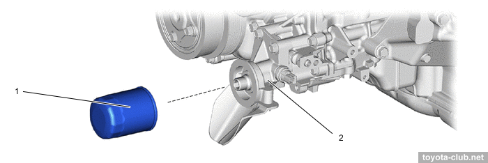
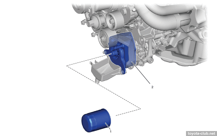
For type'21 a spin-on oil filter is used, the oil cooler is integrated in the filter bracket.
|
1 - oil filter, 2 - oil filter bracket
|
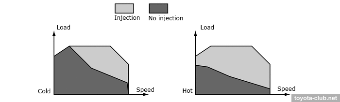
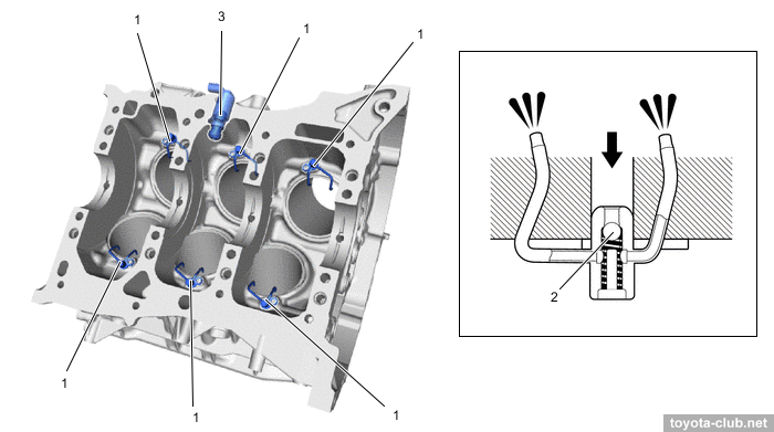
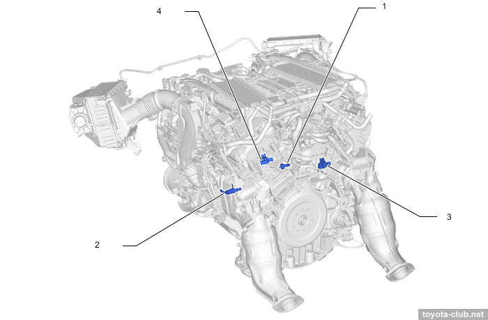
To lubricate and cool the pistons dual oil nozzles are installed. For type'17 the oil supply is controlled by ECM via control valve. To avoid fuel condensation and deposit formation due to insufficient piston temperature, the oil supply to the nozzles is cut-off at cold engine. For type'21 this part of the lubrication system is simplified.
|
1 - oil jet, 2 - check valve, 3 - oil pressure switching valve
|
|
1 - oil jet, 2 - valve, 3 - ECM, 4 - oil pressure switching valve, 5 - spring. a - engine oil (from oil pump)
|
|
1 - oil jet, 2 - valve, 3 - oil pressure switching valve, 4 - spring. a - engine oil (from oil pump)
|
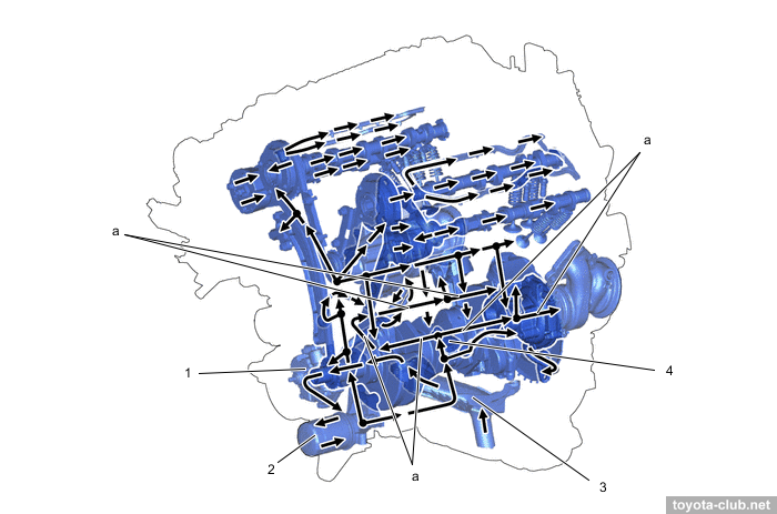
The oil level sensor is installed in the crankcase (functionally, a low-level sensor switch).
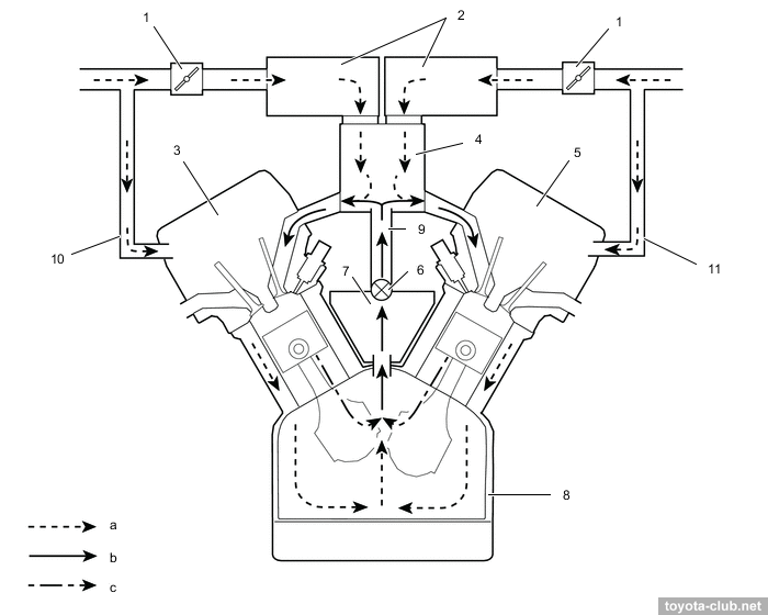
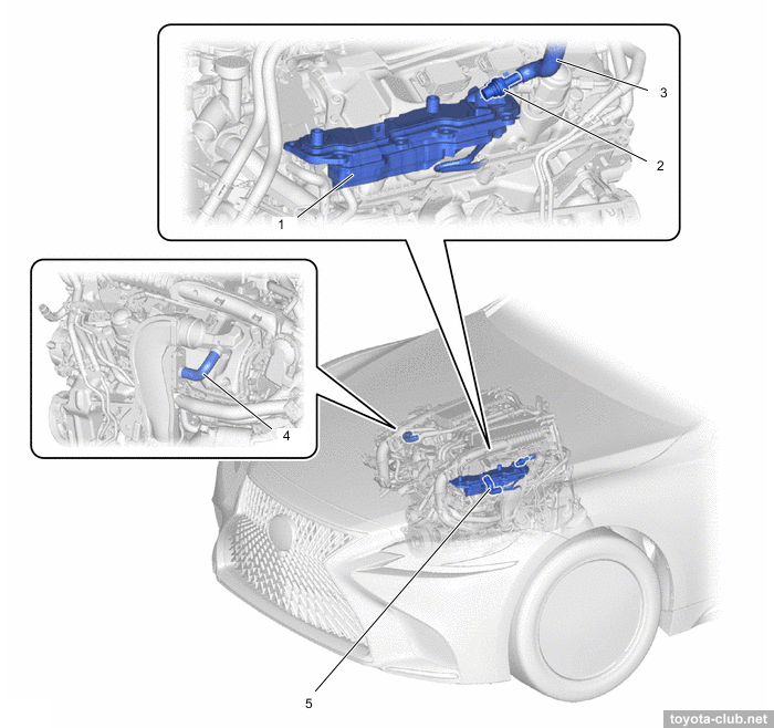
The crankcase ventilation system uses a large oil separator.
|
1 - throttle body, 2 - intake air surge tank with intercooler, 3 - cylinder head cover, 4 - intake manifold, 5 - cylinder head cover LH, 6 - PCV valve, 7 - oil mist separator, 8 - cylinder block, 9 - ventilation hose, 10 - ventilation hose 2, 11 - ventilation hose 3.
a - fresh air, b - blowby gas + fresh air, c - blowby gas
|
|
1 - oil mist separator, 2 - PCV valve, 3 - ventilation hose, 4 - ventilation hose 2, 5 - ventilation hose 3
|
At low load (high vacuum in the intake manifold) the PCV valve closes reducing the gases flow. At high load (low vacuum) the valve opens and gases pass to the intake.
Cooling system
|
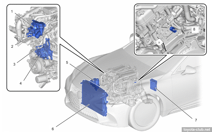
Type'17. 1 - control valve, 2 - coolant temperature sensor (outlet), 3 - coolant temperature sensor (inlet), 4 - pump, 5 - radiator reserve tank, 6 - radiator, 7 - ECM, 8 - coolant temperature sensor (cylinder head)
|
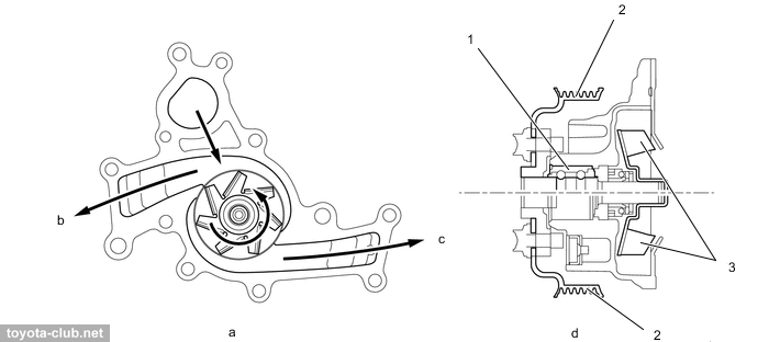
The coolant pump is traditional, belt-driven, mounted on the timing chain cover.
|
1 - bearing, 2 - pulley, 3 - rotor. b - to left bank (B2), c - to right bank (B1)
|
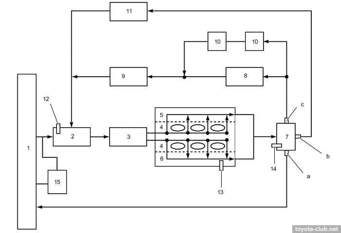
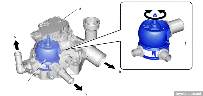
The main innovation is the control valve that commutes the three channels of the cooling system and regulates the flow of coolant depending on the engine operating conditions. The valve is driven by an electric motor through a 3-stage gearbox, with feedback by the valve position sensor. The near-located thermostat performs backup and safety functions.
|
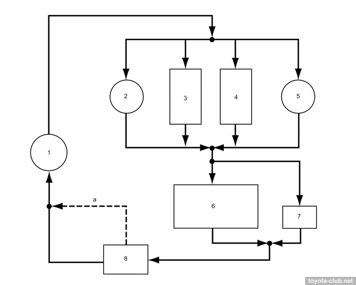
Type'17. 1 - radiator, 2 - inlet, 3 - coolant pump, 4 - cylinder block, 5 - cylinder head, 6 - cylinder head LH, 7 - coolant control valve, 8 - heater radiator, 9 - heater coolant pump (models with stop-start system), 10 - throttle body, 11 - oil cooler, 12 - coolant temperature sensor (inlet), 13 - coolant temperature sensor (cylinder head), 14 - coolant temperature sensor (outlet), 15 - radiator reserve tank. a - radiator port, b - ATF warmer port, c - heater port.
|
Using the valve, a few operation algorithms of the cooling system are provided:
- no circulation - at low temperature all channels are closed, engine warm-up is maximally fast
- low circulation - the heater port is open and the ATF heater port is gradually opening, the temperature slowly increases, while heating and cooling are provided
- high temperature - the heater port, the ATF heater port and the radiator port (low or medium load, after warm-up) are open, the throughput of the radiator port is adjustable for better economy
- low temperature - the heater port, the ATF heater port and the radiator port (high load) are open, the flow through the radiator port is increased to maintain a low temperature and to prevent knocking
|
1 - ball valve. a - motor and 3-step deceleration gear, b - to radiator, c - to heater radiator unit, d - to ATF cooler
|
There are three coolant temperature sensors - at the inlet, at the outlet (control valve), in the left cylinder head.
Type'17: The fan motor control unit allows to stepless adjust fan speed depending on the coolant temperature, climate control, vehicle speed and engine speed. The fan is single, large-diameter, with a brushless electric motor.
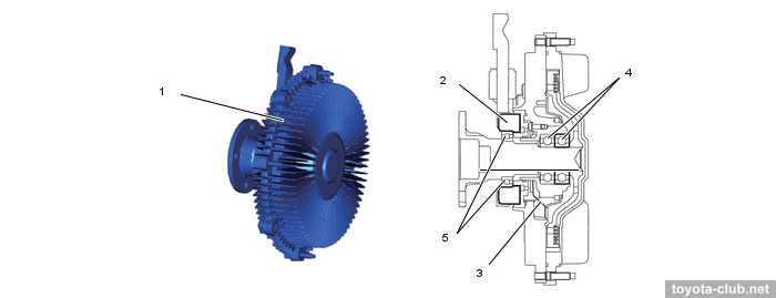
Type'21. The fan is belt driven, but instead of a simple viscous coupling, an electronically controlled fluid clutch is installed, which allows to reduce the fan speed during start-up, warm-up, idle and at low load.
|
Type'21. 1 - fluid coupling, 2 - rotation sensor, 3 - valve, 4 - bearing, 5 - double seal
|
Intake and exhaust
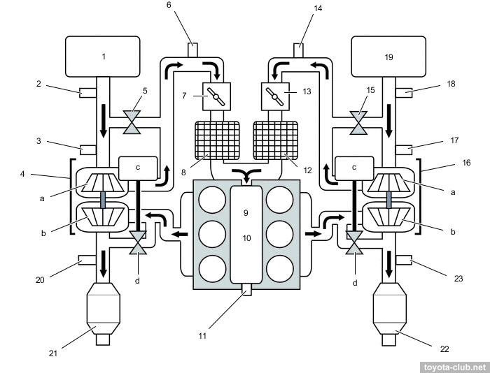
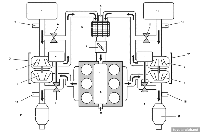
Intake system - Twin Turbo (two parallel turbochargers). Type'17 - with two air-water intercoolers and two throttle valves, type'21 - with single intercooler and single throttle.
.
|
Type'17. 1 - air cleaner LH, 2 - MAF sensor (B2), 3 - vacuum sensor (B2), 4 - turbocharger 1, 5 - air by-pass valve (B2), 6 - boost pressure sensor 1 (B2), 7 - throttle body B2), 8 - intercooler LH, 9 - surge tank, 10 - intake manifold, 11 - boost pressure sensor 3, 12 intercooler RH, 13 - throttle body (B1), 14 - boost pressure sensor (B1), 15 - air by-pass valve (B1), 16 - turbocharger 2, 17 - vacuum sensor (B1), 18 - MAF sensor (B1), 19 - air cleaner RH, 20 - air-fuel ratio sensor (B2S1), 21 - converter LH, 22 - converter RH, 23 - air-fuel ratio sensor (B1S1). a - compressor, b - turbine, c - wastegate valve actuator, d - wastegate valve
|
|
|
Type'21. 1 - air cleaner (left), 2 - intake air flow meter (B2), 3 - turbocharger 1,
4 - air by-pass valve assembly (B2), 5 - boost pressure sensor (B2), 6 - intercooler,
7 - throttle body, 8 - intake air surge tank, 9 - intake manifold, 10 - boost pressure sensor 3, 11 - air by-pass valve assembly (B1), 12 - turbocharger 2, 13 - intake air flow meter (B1), 14 - air cleaner (right), 15 - air-fuel ratio sensor (B2S1), 16 - catalyst (left), 17 - catalyst (right), 18 - air-fuel ratio sensor (B1S1). a - compressor, b - turbine, c - WGT actuator, d - WGT valve |
|
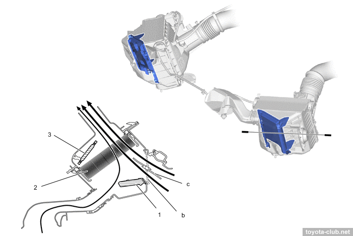
Intake system (type'17). 1 - turbocharger 2, 2 - inlet air cleaner 2, 3 - air cleaner RH, 4 - throttle body (B1), 5 - inlet air cleaner 2, 6 - throttle body (B2), 7 - air cleaner LH, 8 - turbocharger 1, 9 - lower intake manifold, 10 - intake manifold, 11 - intake air surge tank, 12 - air by-pass valve (B1), 13 - air by-pass valve (B2)
|
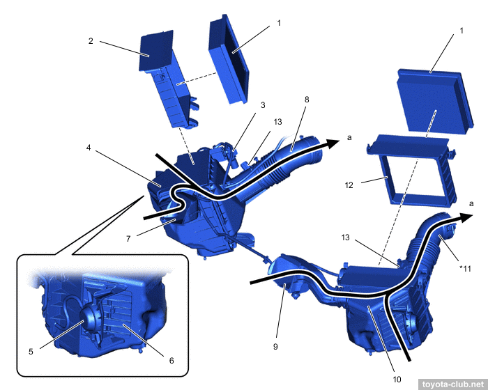
Type'17: AICV flaps are installed at the inlet, that open the air intake to the filters through two channels at high engine speed.
|
Type'17. 1 - air cleaner filter element, 2 - air cleaner cap RH, 3 - vacuum switching valve (AICV), 4 - air cleaner RH, 5 - actuator (AICV), 6 - air intake control valve, 7 - inlet air cleaner 1, 8 - air cleaner hose RH, 9 - inlet air cleaner 2, 10 - air cleaner LH, 11 - air cleaner hose LH, 12 - air cleaner cap LH, 13 - MAF sensor. a - to intake air surge tank with intercooler
|
Inside the filter housing a special fiber inserts provide low level of high-frequency noise and make the engine sound more "premium".
|
1 - sound absorbing material, 2 - air cleaner filter element, 3 - carbon filter.
b - air intake control valve (closed), c - air intake control valve (open)
|
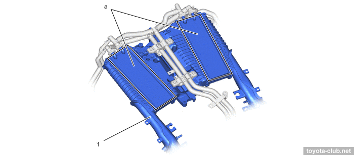
The polymer intake manifold is combined with the intercooler to minimize weight and size.
|
Type'17. 1 - intake air surge tank with intercooler. a - intercooler
|
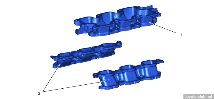
Type'17: The lightweight and thin intake manifold is divided into parts, the diameters and length of the ports are optimized for maximum power output.
|
1 - intake manifold, 2 - lower intake manifold
|
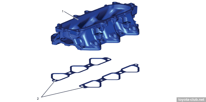
Type'21. The light-alloy intake manifold has a more traditional design.
|
1 - intake manifold, 2 - gasket
|
Turbochargers and intercoolers are proided with a separate cooling system with an additional radiator and electric pump.
|
Type'17. 1 - electric coolant pump, 2 - turbocharger 2, 3 - intercooler RH, 4 - intercooler LH, 5 - turbocharger 1, 6 - intercooler radiator, 7 - sub radiator, 8 - intercooler reserve tank. a - bypass passage
|
|
Intercooler (type'17). 1 - intake air surge tank, 2 - intercooler reserve tank, 3 - intercooler radiator, 4 - sub radiator, 5 - electric coolant pump, 6 - turbocharger 2, 7 - turbocharger 1
|
|
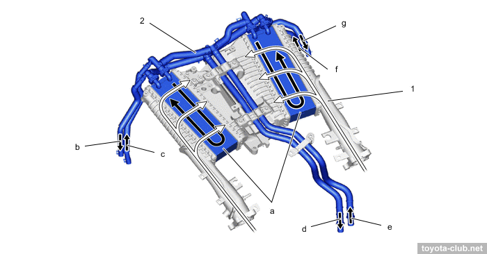
Type'17. 1 - intake air surge tank with intercooler, 2 - coolant by-pass tube 1.
a - intercooler, b - turbocharger 2, c - from turbocharger 2, d - to intercooler radiator, e - to electric coolant pump, f - from turbocharger 1, g - to turbocharger 1
|
|
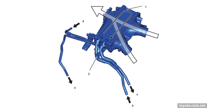
Type'21. 1 - intercooler, 2 - coolant pipe. a - to turbocharger 2, b - from electric pump,
c - to intercooler cooling radiator, d - from turbocharger 1
|
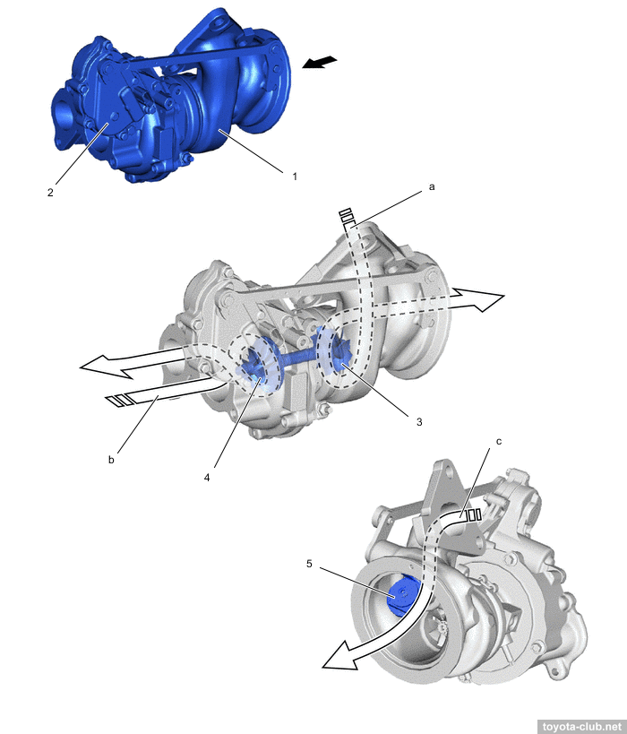
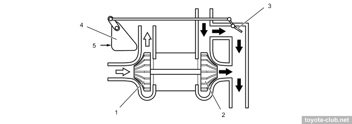
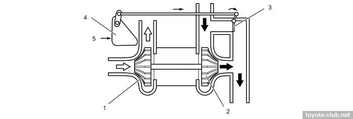
Boost pressure is controlled by electric-driven WGT valve. At light load, the valve is open, reducing pump losses and exhaust back pressure. At high load, the valve is closed, increasing torque and improving the accelerator-response. In addition, WGT opens after start and the exhaust gases pass directly to the catalyst to accelerate its heating.
|
1 - turbocharger, 2 - wastegate valve actuator, 3 - turbine wheel, 4 - compressor wheel, 5 - wastegate valve. a - exhaust gas, b - intake air, c - bypass gas
|
|
Wastegate Valve Opened. 1 - compressor wheel, 2 - turbine wheel, 3 - wastegate valve, 4 - wastegate valve actuator, 5 - ECM
|
|
Wastegate Valve Closed. 1 - compressor wheel, 2 - turbine wheel, 3 - wastegate valve, 4 - wastegate valve actuator, 5 - ECM
|
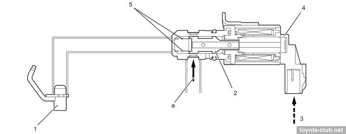
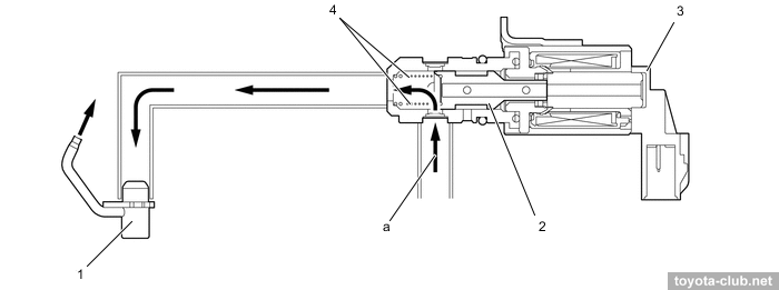
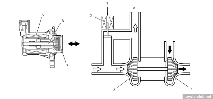
Bypass valves are installed in the inlet to avoid the "ripple effect" when overpressure occurs between the turbocharger and the throttle if the accelerator pedal is suddenly released. The air bypass valve transfers air pressure back to the compressor inlet.
|
Valve closed. 1 - ECM, 2 - air by-pass valve, 3 - compressor wheel, 4 - turbine wheel, 5 - coil, 6 - shaft, 7 - valve. a - to throttle body, b - air by-pass valve
|
|
Valve Open. 1 - ECM, 2 - air by-pass valve, 3 - compressor wheel, 4 - turbine wheel, 5 - coil, 6 - shaft, 7 - valve. a - to throttle body, b - air by-pass valve
|
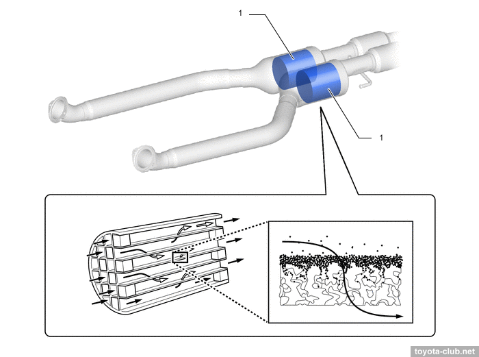
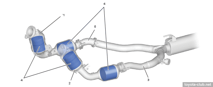
Particle filter
Type'17 is initially equipped with GPF, while type'21 is not yet required to comply with Euro-6.
See details - "Toyota gasoline particulate filters (GPF)".
|
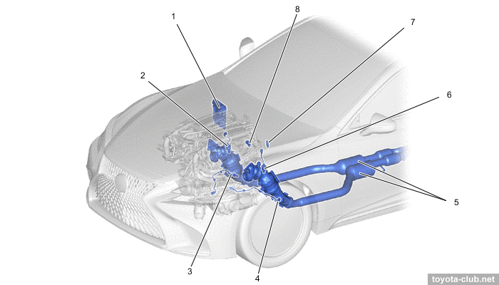
1 - ECM, 2 - air-fuel ratio sensor (B1S1), 3 - air-fuel ratio sensor (B1S2), 4 - air-fuel ratio sensor (B2S1), 5 - front exhaust pipe, 6 - air-fuel ratio sensor (B2S2), 7 - differential pressure sensor (B2), 8 - differential pressure sensor (B1).
|
|
1 - particle filter. a - exhaust gases, b - soot or ash.
|
|
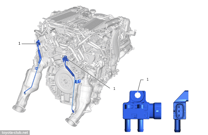
1 - differential pressure sensor
|
|
Type'21. 1 - catalyst (left), 2 - catalyst (right), 3 - center exhaust pipe,
4 - TWC catalyst, 5 - front exhaust pipe
|
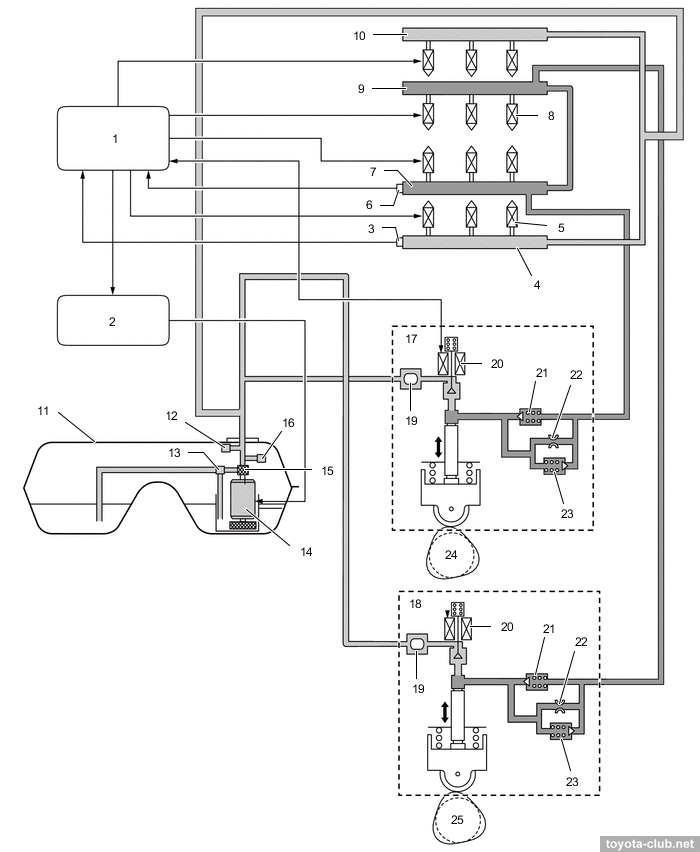
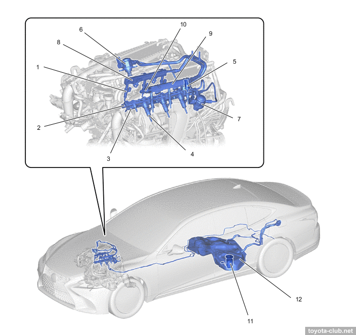
Fuel system (D-4ST)
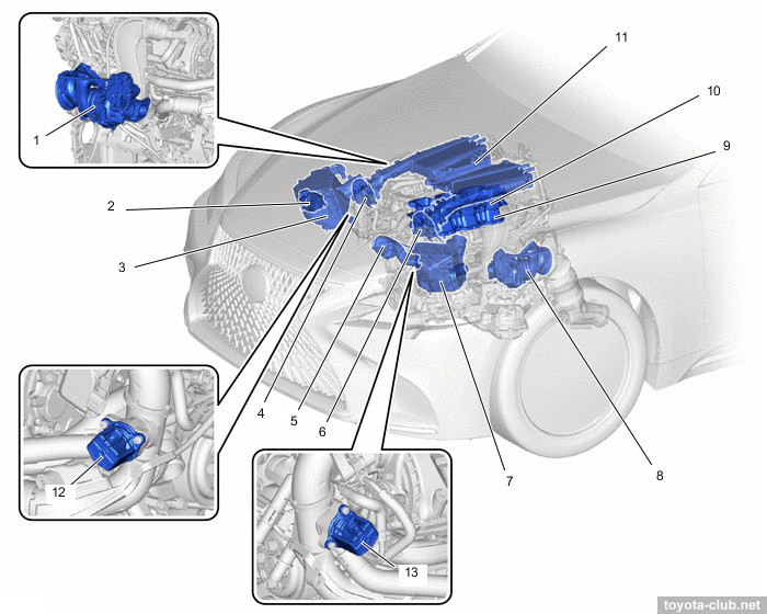
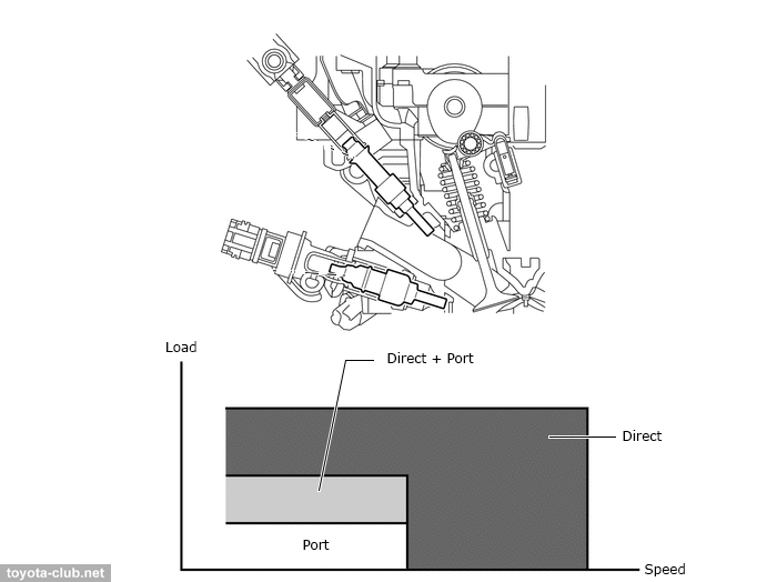
Fuel injection - combined: directly in the combustion chamber and multipoint in the inlet ports.
|
1 - ECM, 2 - fuel pump control ECU, 3 - fuel pressure sensor (low pressure), 4 - fuel delivery pipe 1 LH (port injection), 5 - port fuel injector, 6 - fuel pressure sensor (high pressure), 7 - fuel delivery pipe 2 LH (direct injection), 8 - direct fuel injector, 9 - fuel delivery pipe 2 RH (direct injection), 10 - fuel delivery pipe 1 RH (port injection), 11 - fuel tank, 12 - fuel main valve (high pressure), 13 - jet pump, 14 - fuel pump (low pressure), 15 - fuel filter, 16 - fuel main valve (low pressure), 17 - fuel pump (high pressure, B2), 18 - fuel pump (high pressure, B1), 19 - fuel pressure pulsation damper, 20 - spill control valve, 21 - check valve, 22 - orifice, 23 - relief valve, 24 - exhaust camshaft LH, 25 - exhaust camshaft RH
|
At small and medium load, any of three options can be used - in-port, direct or combined - that allow to create a homogeneous air-fuel mixture and maintain stable combustion. Under a heavy load use direct fuel injection - the evaporation of the fuel in the cylinder filling mass improves and reduces the tendency to knock.
Immediately after a cold start, a combination of in-port and direct injection allows to create a heterogeneous mixture in the cylinder, and due to the retarded ignition increase the temperature of the exhaust gases, accelerating the heating of the catalyst.
|
|
|
1 - port fuel injector, 2 - fuel delivery pipe 2 RH (direct injection), 3 - fuel delivery pipe 2 LH (direct injection), 4 - direct fuel injector, 5 - fuel pressure sensor (high pressure), 6 - fuel pump (high pressure, B1), 7 - fuel pump (high pressure, B2), 8 - fuel delivery pipe 1 RH (port injection), 9 - fuel delivery pipe 1 LH (port injection), 10 - fuel pressure sensor (low pressure), 11 - fuel suction tube, 12 - fuel tank
|
Fuel pump (low pressure) delivers fuel from the tank to the high pressure fuel pump and to the low pressure injectors. Using the PWM signal, the pump control unit provides stepless speed control, providing the required flow rate. An additional function is to turn off the pump when the SRS is triggered.
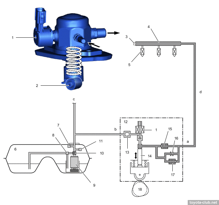
High pressure fuel pump - single-plunger with control valve, relief valve, check valve and pulsation damper at inlet. It is mounted on the valve cover and is driven by a cam with 4 protrusions located on the exhaust camshaft . The fuel pressure is regulated in the range 2.4-20 MPa depending on driving conditions and about 4 MPa at idle.
- At inlet stroke the plunger moves downward and fuel draws into the pumping chamber.
- At the beginning of the compression stroke part of the fuel is returned while control valve is open (the specified fuel pressure is set).
- At the end of the compression stroke control valve is closed and the pressurized fuel through the check valve is supplied into the fuel rail.
- If the pressure in the rail becomes abnormally high, a mechanical relief valve opens to dump part of the fuel back to the pump.
|
1 - spill control valve, 2 - roller lifter (fuel pump), 3 - fuel pressure sensor (high pressure), 4 - fuel delivery pipe 2 (direct injection), 5 - direct fuel injector, 6 - fuel tank, 7 - fuel main valve, 8 - jet pump, 9 - fuel pump (low pressure), 10 - fuel filter, 11 - fuel main valve, 12 - fuel pump (high pressure), 13 - fuel pressure pulsation damper, 14 - plunger, 15 - check valve, 16 - orifice, 17 - relief valve, 18 - exhaust camshaft. a - high-pressure fuel system, b - low-pressure fuel system, c - to fuel delivery pipe (port injection), d - pipe
|
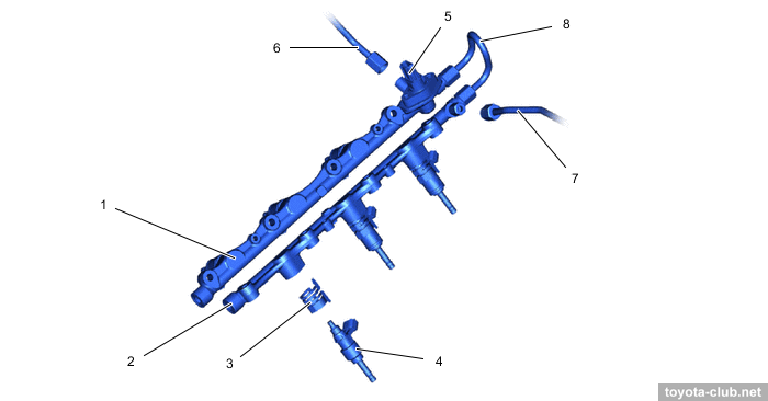
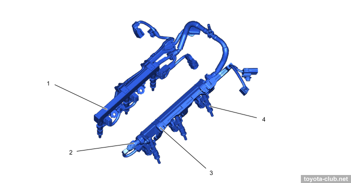
Fuel rail (high pressure) - made of forged steel, contains fuel pressure sensor to provide feedback. Injectors are held by spring holders that reduce vibration and prevent them from moving during starting (when the pressure in the cylinder is higher than the fuel pressure in the rail).
|
1 - fuel delivery pipe 2 RH (direct injection), 2 - fuel delivery pipe 2 LH (direct injection), 3 - nozzle holder clamp, 4 - direct fuel injector, 5 - fuel pressure sensor (high pressure), 6 - fuel pipe 1, 7 - fuel pipe 2, 8 - fuel pipe 3
|
Fuel rail (low pressure) - steel-stamped; its walls themselves serve as a damper for fuel pressure pulsations. The pressure sensor is installed in the left rail.
|
1 - fuel delivery pipe 1 RH (port injection), 2 - fuel pressure sensor (low pressure), 3 - fuel delivery pipe 1 LH (port injection), 4 - port fuel injector
|
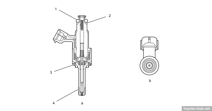
Injectors (high pressure) - with a 6-point nozzle, inject fuel into the cylinders as complex shape torch for maximum atomization of gasoline, forming a vertical vortex in the cylinder. PTFE seal rings further reduce nozzle noise and vibration.
|
1 - o-ring, 2 - backup ring, 3 - insulator, 4 - teflon shaft seal
|
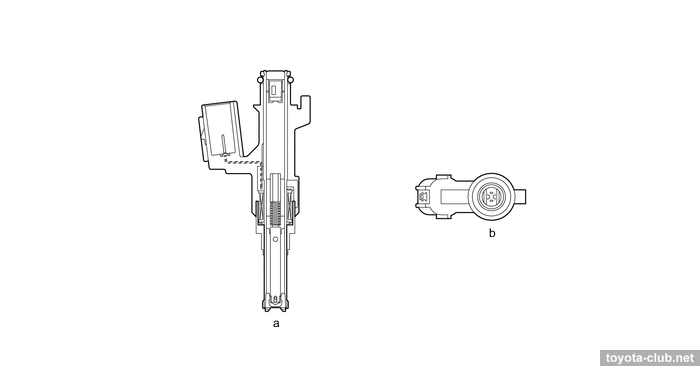
Injectors (low pressure) - with a long 10-point nozzle that delivers fuel to the air stream and minimizes its entry to the port walls.
|
a - port fuel injector, b - injection hole
|
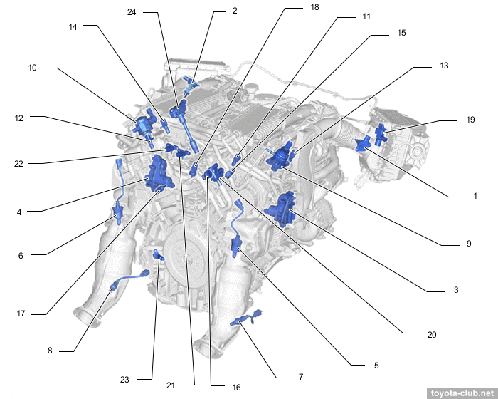
Control system
All the components are quite traditional and already described in our previous reviews.
|
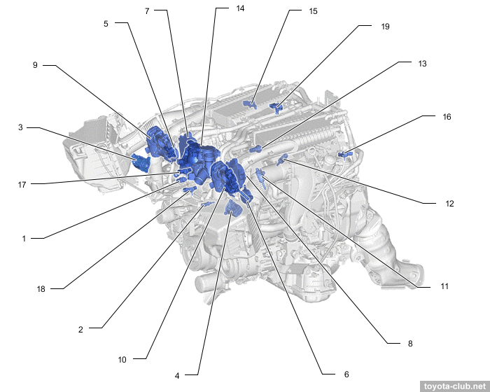
Type'17. 1 - engine coolant temperature sensor (outlet), 2 - engine coolant temperature sensor (inlet), 3 - air by-pass valve (B1), 4 - air by-pass valve (B2), 5 - VVT-i solenoid (B1), 6 - VVT-i solenoid (B2), 7 - VVT-iE motor (B1), 8 - VVT-iE motor (B2), 9 - throttle body (B1), 10 - throttle body (B2), 11 - direct fuel injector, 12 - port fuel injector, 13 - fuel pressure sensor 2 (low pressure), 14 - coolant control valve, 15 - vacuum sensor (B1), 16 - vacuum sensor (B2), 17 - boost pressure sensor 1 (B1), 18 - boost pressure sensor 1 (B2), 19 - boost pressure sensor 3
|
|
|
Type'17. 1 - MAF sensor (B1), 2 - MAF sensor (B2), 3 - wastegate valve actuator (B1), 4 - wastegate valve actuator (B2), 5 - air-fuel ratio sensor (B1S1), 6 - air-fuel ratio sensor (B2S1), 7 - air-fuel ratio sensor (B1S2), 8 - air-fuel ratio sensor (B2S2), 9 - fuel pump (high pressure) (B1), 10 - fuel pump (high pressure) (B2), 11 - camshaft position sensor (intake) (B1), 12 - camshaft position sensor (intake) (B2), 13 - camshaft position sensor (exhaust) (B1), 14 - camshaft position sensor (exhaust) (B2), 15 - knock control sensor (B1), 16 - knock control sensor (B2), 17 - engine coolant temperature sensor (cylinder head), 18 - fuel pressure sensor (high pressure)
|
|
Type'17. 1 - oil pressure sender gauge, 2 - oil pressure switching valve, 3 - differential pressure sensor (B1), 4 - differential pressure sensor (B2)
|
Components
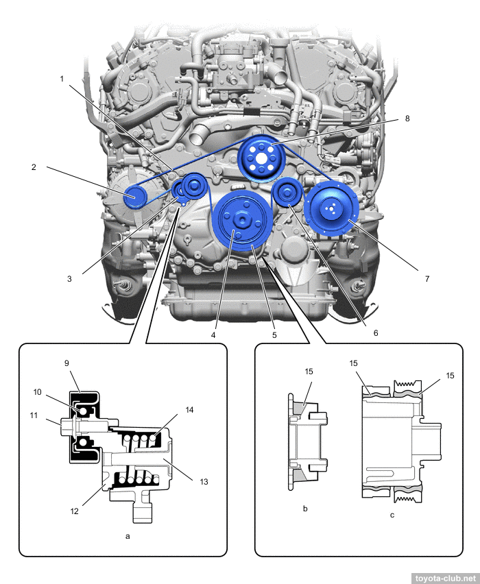
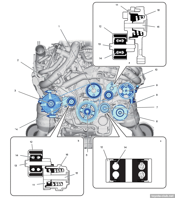
The drive belt of the smallest possible width is equipped with an automatic tensioner. A torsional vibration damper is installed in the generator pulley, the crankshaft pulley is equipped with two rubber dampers. Type'21 received two drive belts with similar friction tensioners.
|
Type'17. 1 - v-belt, 2 - generator pulley, 3 - belt tensioner, 4 - crankshaft damper, 5 - crankshaft pulley, 6 - idler pulley, 7 - air conditioner compressor pulley, 8 - coolant pump pulley, 9 - idler pulley, 10 - ball bearing, 11 - pulley bolt, 12 - arm, 13 - shaft, 14 - spring, 15 - rubber damper
|
|
Type'21. 1 - coolant pump pulley, 2 - belt 1, 3 - generator pulley, 4 - tensioner 1, 5 - crankshaft pulley, 6 - air conditioning compressor pulley, 7 - idler pulley, 8 - belt 2, 9 - power steering pump pulley, 10 - tensioner 2, 11 - arm, 12 - idler pulley, 13 - pulley bolt, 14 - ball bearing, 15 - shaft, 16 - spring
|
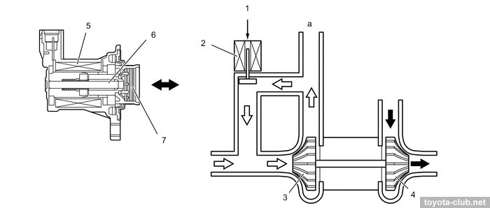
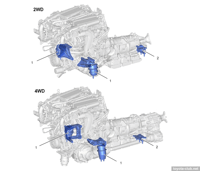
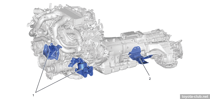
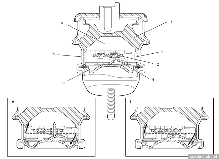
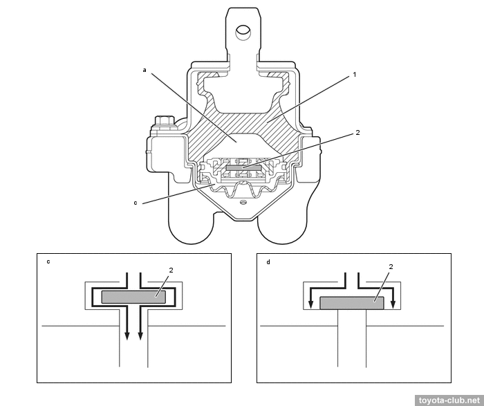
Semi-active mountings - designed to dampen engine vibrations. Type'17: At idle the pressure fluctuations are small, the fluid circulates freely through both channels, and the mount characteristic is aimed to isolate the body from engine vibrations. While driving the pressure fluctuations increase, the diaphragm blocks channel 2, the fluid circulates only through channel 1 (which should improve vehicle driveability). For type'21, the channel between the chambers is opened or closed by a movable plate.
|
Type'17. 1 - front mounting insulator, 2 - rear mounting insulator. a - 2WD, b - 4WD
|
|
Type'21. 1 - front engine mounting insulator, 2 - rear engine mounting insulator
|
|
Type'17. 1 - body rubber, 2 - movable membrane. a - main chamber, b - passage 1, c - sub-chamber, d - passage 2, e - idling (small vibrations), f - driving (large vibrations)
|
|
Type'21. 1 - body rubber, 2 - movable plate. a - main chamber, b - sub-chamber, c - idling (small vibrations), d - driving (large vibrations)
|
Toyota engines review
·
AZ ·
MZ ·
NZ ·
SZ ·
ZZ ·
AR ·
GR ·
KR ·
NR ·
ZR ·
AD ·
GD ·
ND ·
VD ·
A25.M20 ·
F33 ·
G16 ·
M15 ·
V35 ·
|
|
|