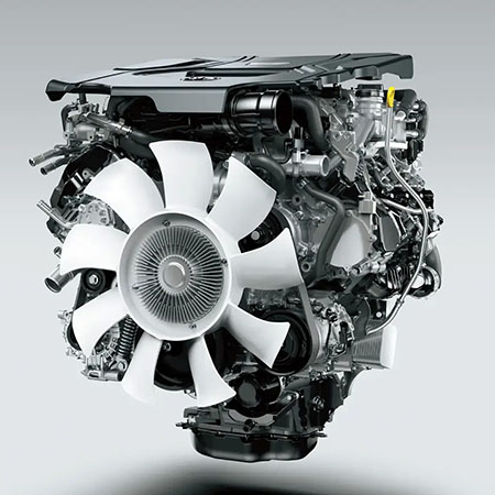
Detailed review of the technical features of the new 3.3 diesel engine for Toyota Land Cruiser 300 and Lexus LX.
Specifications
Engine
Displacement, cm3
Bore x Stroke, mm
Compression ratio
Output, PS
Torque, Nm
-
F33A-FTV
3346
86.0 x 96.0
15.4
308 / 4000
700 / 1600-2600
CSC
299 / 3600-4200
700 / 1600-2600
CSC RUS
306 / 4000
700 / 1600-2600
non-CSC
Engine weight ~266 kg.
Emissions grades: Euro 2-3-4-5, BS 6
Engine mechanical
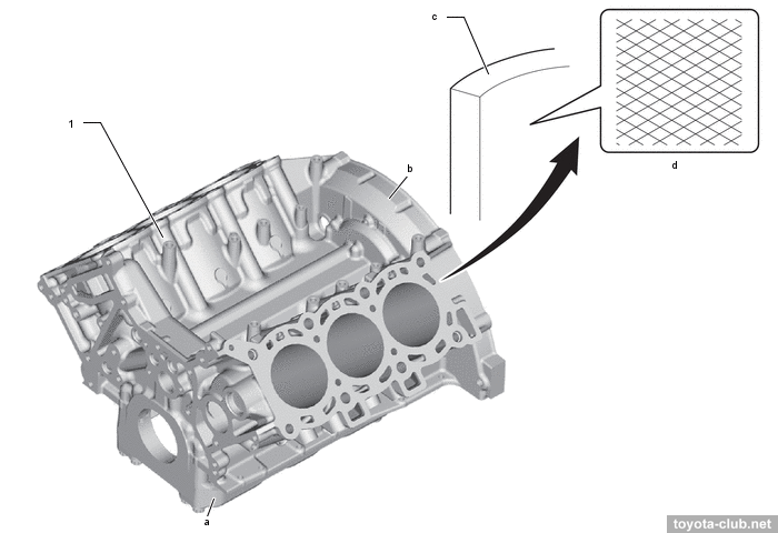
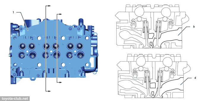
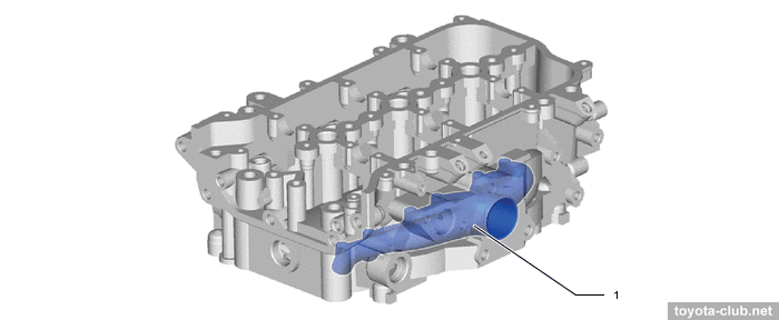
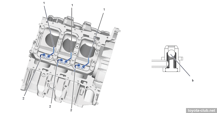
The engine obtained a cast-iron cylinder block with a closed deck. The main bearing caps are integrated into a bearing beam carrier. At the rear side, the banks are connected by a bridging arch to increase rigidity.
1 - cylinder block. a - bearing beam, b - arch shape, c - cylinder bore, d - bore cross hatch
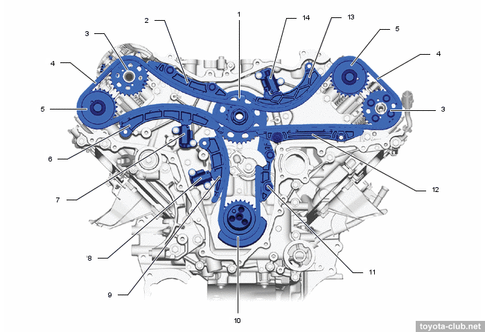
The angle between cylinder block banks is 90° - for the first time on Toyota V6. The advantages are unification with the V8, less engine height, but perhaps the main thing in this case is a large free space between the banks. The downside is a poor engine balance. Therefore,
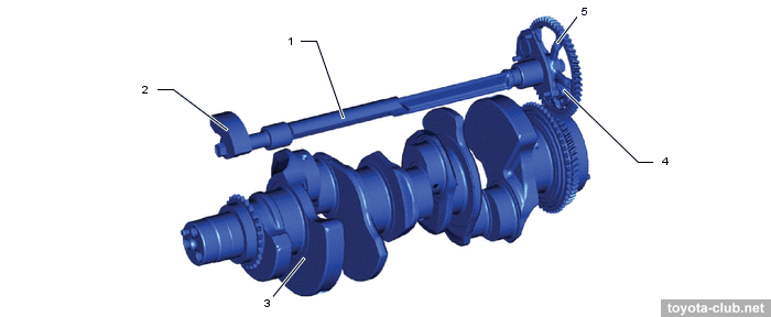
also for the first time for Toyota V6s a split balancer shaft installed, driven by crankshaft.
What does the V8 have to do with it? - for some reason the bore and stroke of the F33 correspond to 1VD-FTV engine.
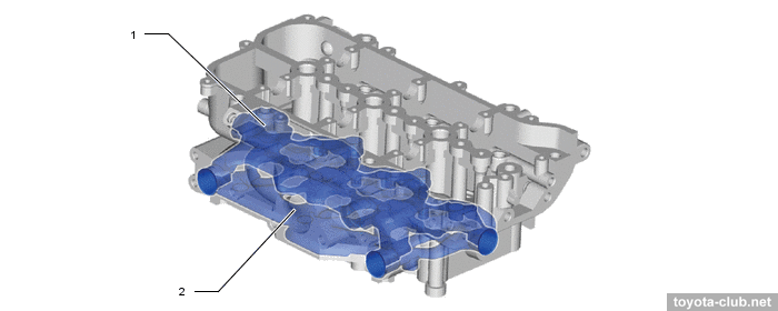
Cylinder head - with double-stage cooling jacket, with integrated exhaust manifold.
1 - cylinder head
1 - exhaust manifold
1 - water jacket (upper side), 2 - water jacket (lower side)
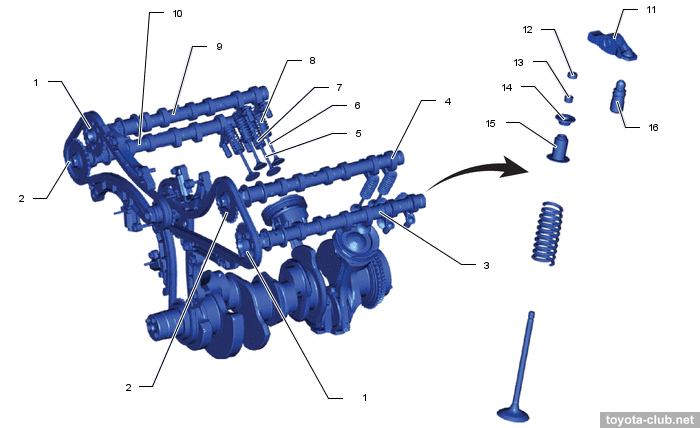
Valve mechanism - DOHC 24V: double camshafts in the heads and four valves per cylinder. Camshafts - cast iron, hollow type. There are valve adjusters and roller rockers in the valve mechanism.
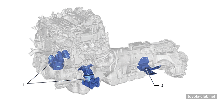
The powertrain is suspended with three mountings, the front ones are hydraulic semi-active.
1 - front mounting insulator, 2 - rear mounting insulator
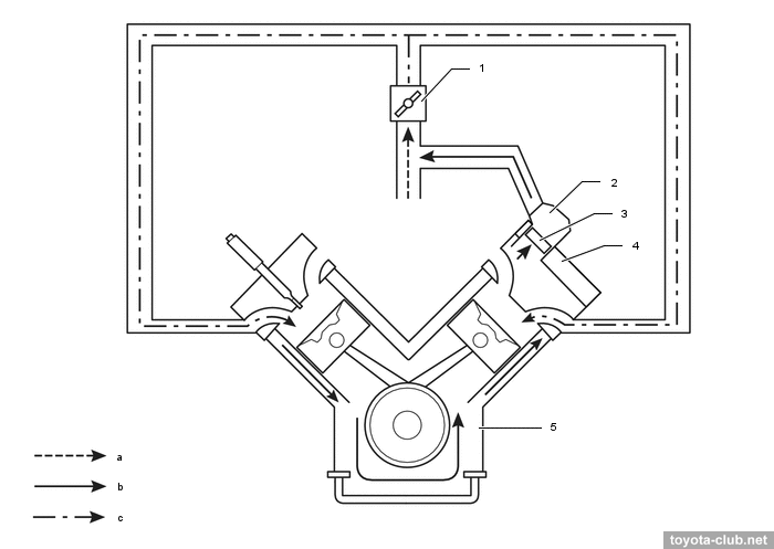
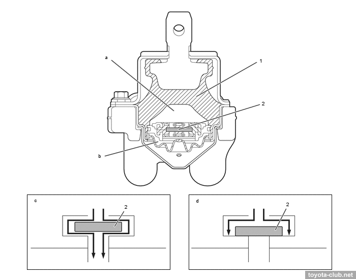
At idle, the vibration amplitude is small, the movable plate does not block the channel between the main and sub chambers: the liquid circulates between the chambers, providing "softness" of the mounting and vibration suppression. When driving, the amplitude increases, the movable plate closes the channel: the liquid does not circulate, providing "rigidity" of the mounting and improving the driving characteristics.
1 - body rubber, 2 - movable plate. a - main chamber, b - sub-chamber, c - idling (small vibrations), d - driving (large vibrations)
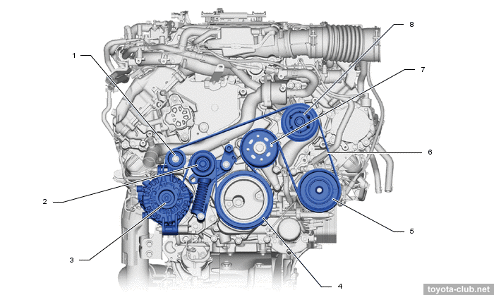
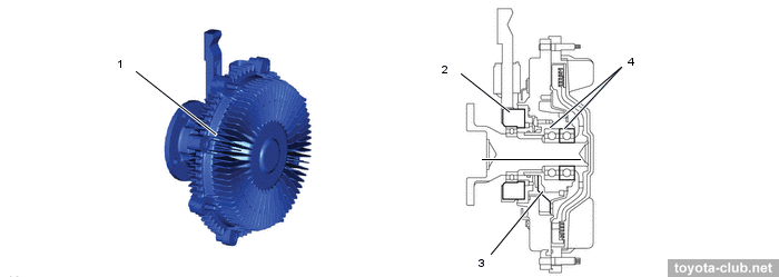
The fan has a belt drive, but instead of a simple viscous, a so-called controlled electro-viscous clutch is installed, which allows to "intelligently" reduce the fan speed when starting, warming up, at idle and at low load. Details about the operation of such clutches can be found using the keywords "Borg Warner Visctronic".
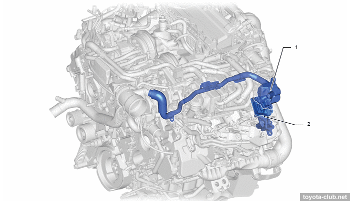
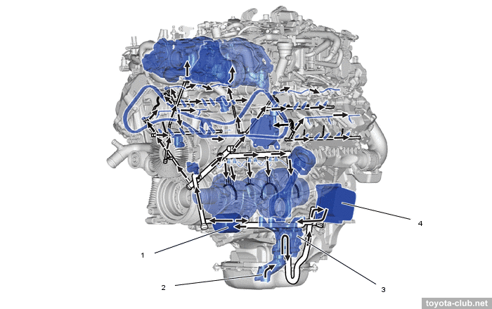
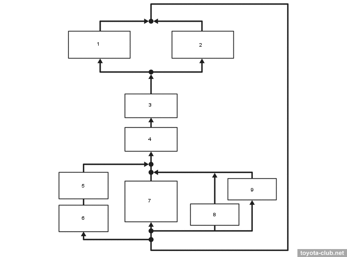
Literally the second cooling system with its own electric pump and two radiators is tied to an intercooler (also cools turbochargers, AdBlue supply module and exhaust fuel injector).
1/2 - intercooler cooling radiator. a - inlet port, b - outlet port
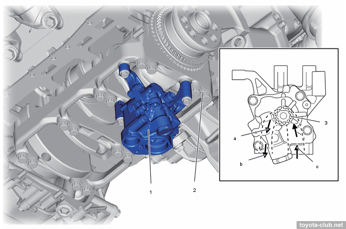
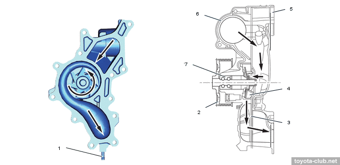
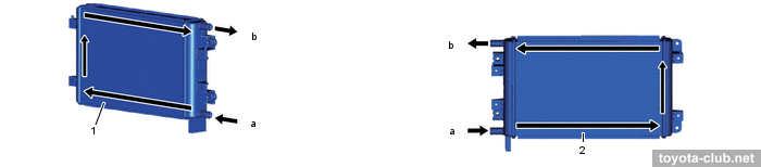
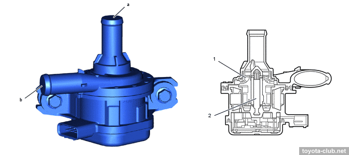
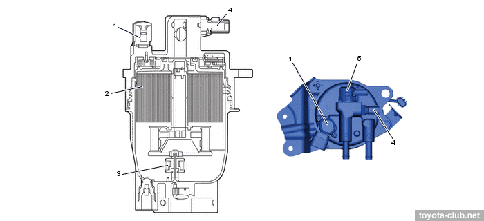
The electric pump is a compact brushless, the speed is regulated by the engine ECU.
1 - rotor, 2 - shaft. a - inlet, b - outlet
Intake and exhaust
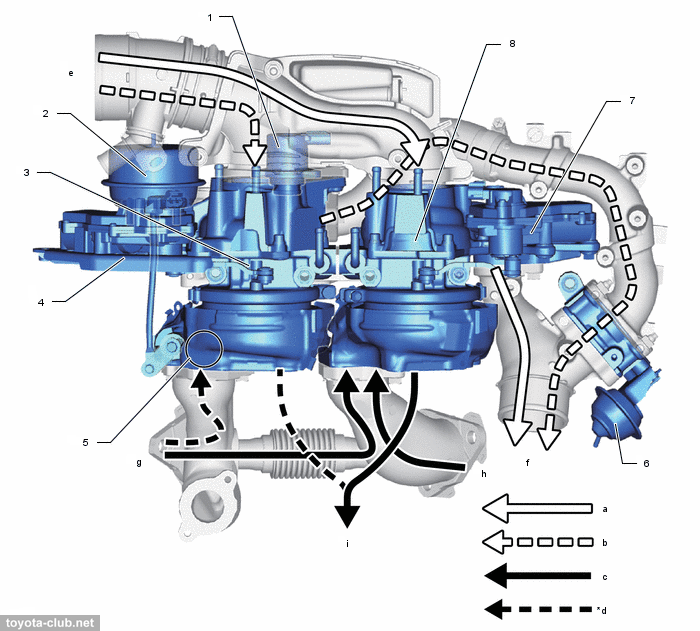
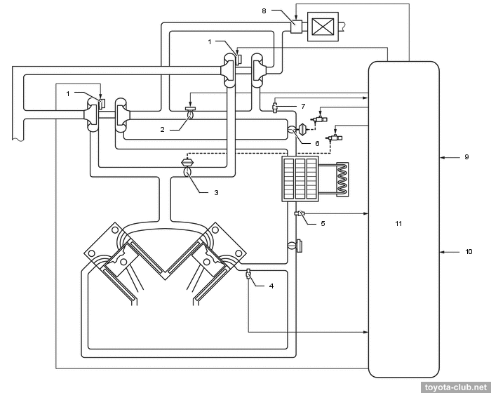
A pair of turbochargers with variable geometry (VGT or VNT) at low speeds operate in single-turbo mode, at high speeds as twin-turbo.
1 - air by-pass valve, 2 - actuator, 3 - turbocharger 2, 4 - turbocharger 2 variable nozzle motor, 5 - exhaust control valve, 6 - intake air control valve, 7 - turbocharger variable nozzle motor, 8 - turbocharger. a - air (single/twin turbo mode), b - air (twin turbo mode), c - exhaust gas (single/twin), d - exhaust gas (twin), e - from air cleaner, f - to intercooler, g - from cylinder head lh, h - from cylinder head, i - to exhaust pipe
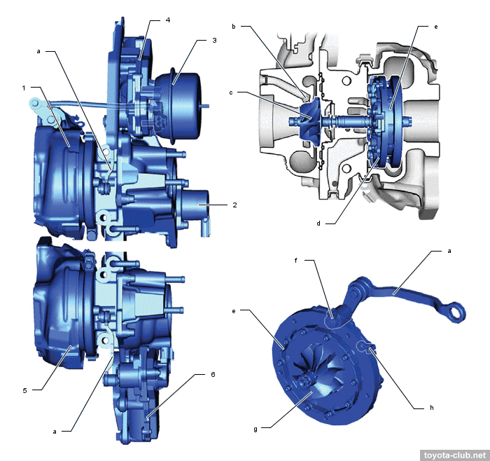
The variable geometry of the vanes allows to maintain an optimal boost pressure in a wide range of engine speed, reduce back pressure at high speeds, and increase power at low speeds.
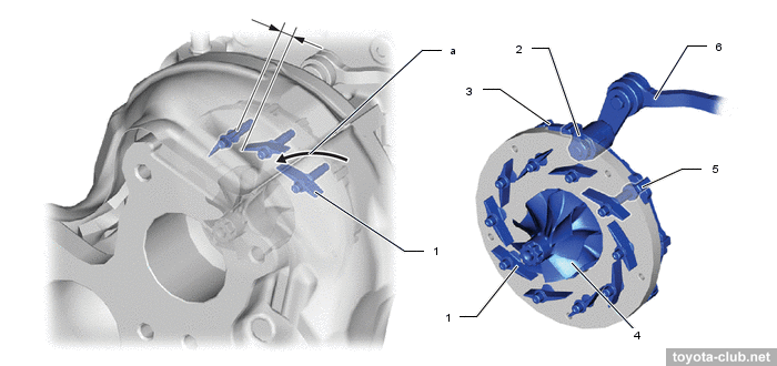
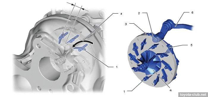
1 - turbocharger 2, 2 - air by-pass valve, 3 - actuator, 4 - turbocharger 2 VGT motor,
5 - turbocharger 1, 6 - turbocharger 1 VGT motor. a - linkage, b - water jacket, c - compressor wheel, d - unison ring, e - nozzle vane, f - drive arm, g - turbine wheel, h - driven arm
- At low load or low engine speed actuator moves the control ring and turns pivotally connected vanes to partially closed position. This increases the speed of gas entering the turbine, increases the boost pressure and increases engine torque.
- At high load or med-to-high speed vanes are moved to the open position, allowing maintain the desired boost pressure and reduce resistance at exhaust.
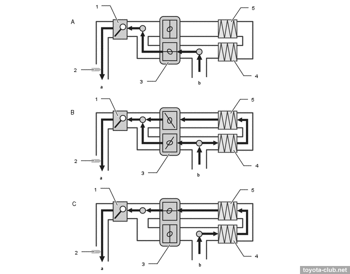
Turbocharger operation modes switching (2 Way Twin Turbo)
1 - DC motor, 2 - air by-pass valve (ABV), 3 - exhaust control valve (ECV),
4 - turbo pressure sensor, 5 - intake air temperature switch (intercooler outlet),
6 - intake air control valve (IACV), 7 - turbo pressure sensor (compressor outlet),
8 - mass air flow meter, 9 - injector, 10 - crank position sensor, 11 - ECM
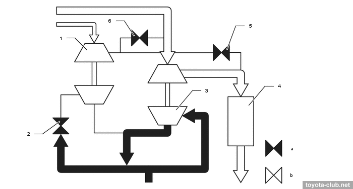
- Single-turbo mode - the exhaust gas supply to turbocharger 2 is shut-off, the air passages from compressor 2 are closed.
1 - turbocharger 2, 2 - exhaust control valve, 3 - turbocharger 1, 4 - intercooler, 5 - intake air control valve, 6 - air by-pass valve. a - valve close, b - valve open
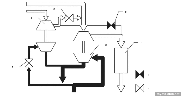
- Smooth mode switching performs by ECV valve opening and the turbocharger 2 operation in advance. Fast mode switching performs by ABV valve opening, as a result, air enters the turbocharger inlet and quickly increases the speed of the turbine.
1 - turbocharger 2, 2 - exhaust control valve, 3 - turbocharger 1, 4 - intercooler, 5 - intake air control valve, 6 - air by-pass valve. a - valve close, b - valve open
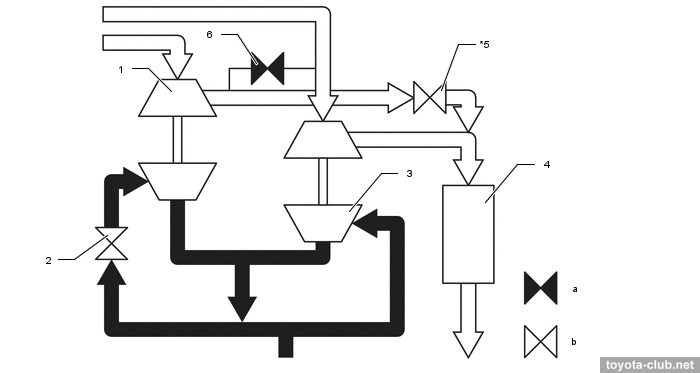
- Twin-turbo mode - ECV and IACV are open to supply air from turbocharger 2 to the engine.
1 - turbocharger 2, 2 - exhaust control valve, 3 - turbocharger 1, 4 - intercooler, 5 - intake air control valve, 6 - air by-pass valve. a - valve close, b - valve open
A cooling jacket is made in the compressor housing to reduce the temperature of the air duct walls and reduce the amount of deposits.
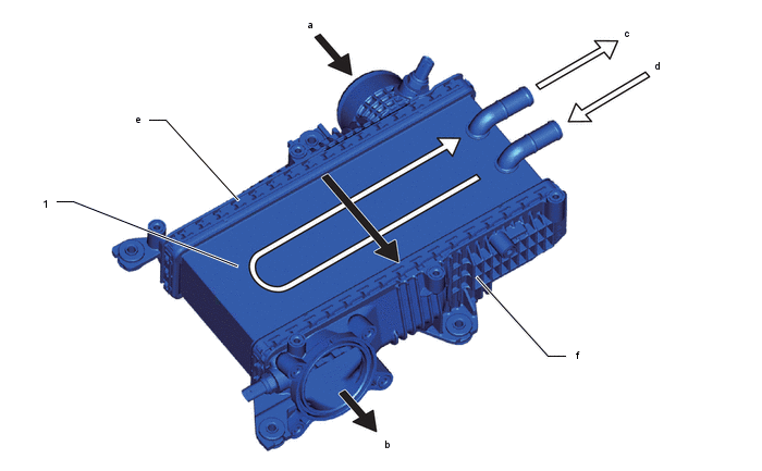
A large intercooler with autonomous liquid cooling is installed.
1 - intercooler. a - from turbocharger, b - to throttle, c - to electric pump, d - from intercooler cooling radiator, e - in-tank, f - out-tank
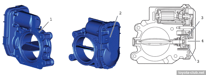
The intake contains a throttle valve with a DC motor and a Hall-effect position sensor.
1 - throttle valve, 2 - throttle position sensor, 3 - magnetic yoke, 4 - Hall IC
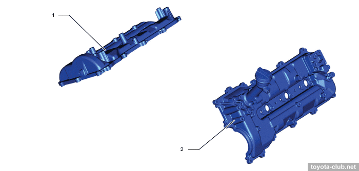
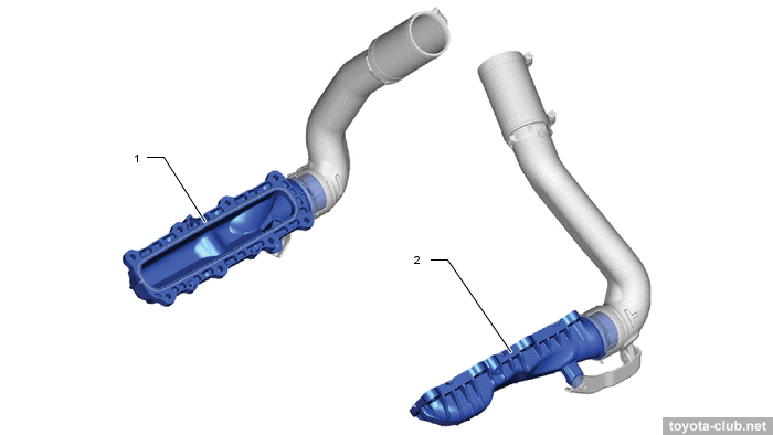
The intake manifold is made of heat-resistant resin.
1/2 - intake manifold
Fuel system / Engine control
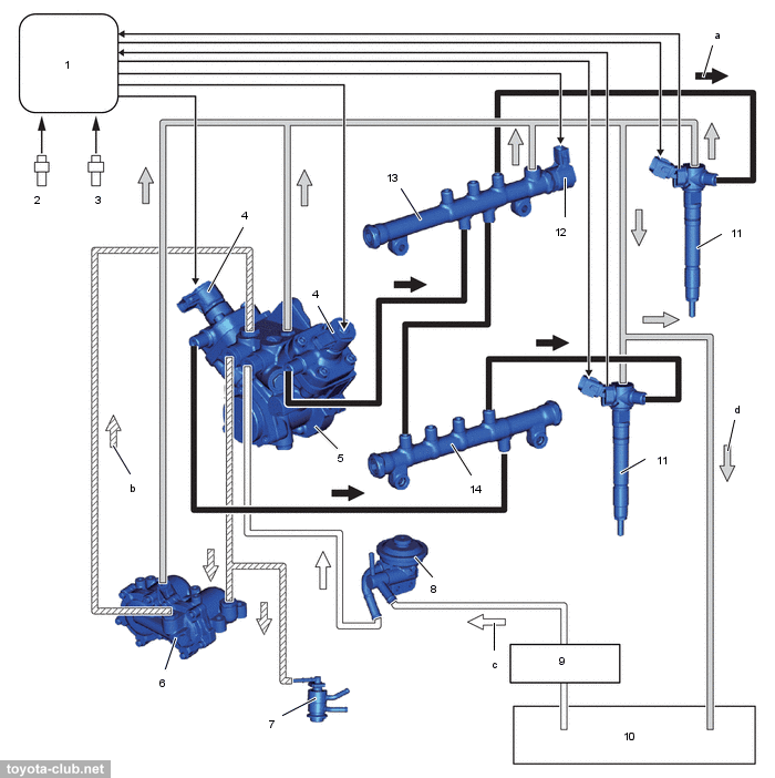
Common Rail type fuel system - the fuel is supplied by high pressure pump in a common rail and then is injected into the cylinders via the electronically controlled injectors. The injection pressure - 32-270 MPa. The system is branded i-ART (intelligent-Accuracy Refinement Technology)
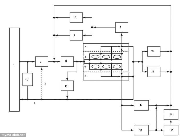
Fuel system (DPF version). 1 - ECM, 2 - crankshaft position sensor, 3 - camshaft position sensor,
4 - pre-stroke control valve, 5 - injection pump, 6 - fuel filter, 7 - exhaust injector, 8 - priming pump, 9 - fuel filter, 10 - fuel tank, 11 - injector, 12 - pressure discharge valve, 13 - common-rail (B1), 14 - common-rail (B2). a - fuel (high pressure), b - fuel (feed pressure), c - fuel (suction), d - fuel (return)
•
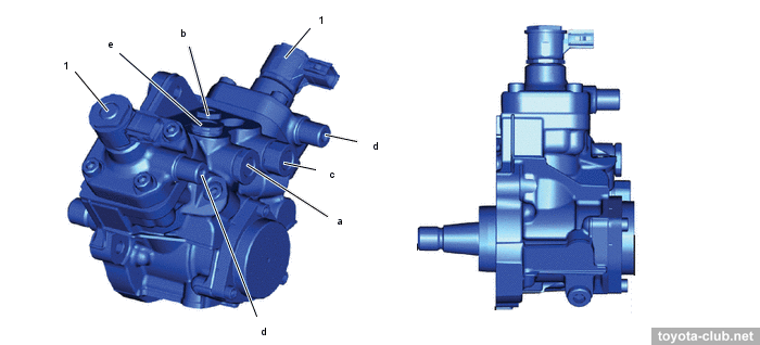
Injection pump - HP5D type, two-chamber, with two control valves. Fuel pressure is controlled by metering the fuel supply at the injection pump inlet and metering the drain through the pressure relief valve.
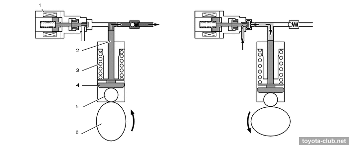
1 - pre-stroke control valve. a - to exhaust injector / pressurized fuel filter, b - outlet (to fuel tank), c - inlet (priming pump), d - to common-rail, e - from pressurized fuel filter
Rotating cam via follower moves the plunger upwards. If the control valve is closed, the pressure increases and the fuel from the pump flows into the rail. ECM controls the timing of control valve closing and thus provides a target level of pressure in the fuel rail. If the plunger is not pushed by cam, it is returned downward by the spring force.
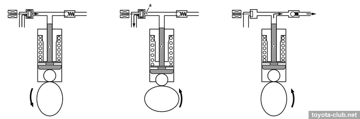
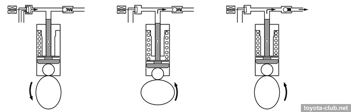
- Late closing of the control valve increases fuel discharge to inlet and reduces supply volume.
- Early closing of the control valve increases supply volume.
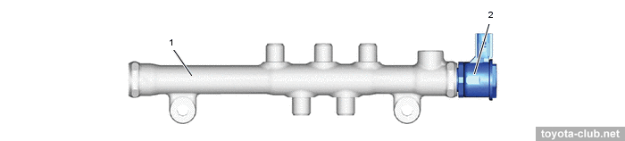
• There are fuel pressure sensor and pressure discharge valve in the fuel rail. Electronically controlled valve opens and closes by a signal from the control unit, moreover, it can function of emergency pressure relief.
1 - common-rail (B1), 2 - common-rail (B2), 3 - pressure discharge valve.
a - to injector, b - from injection pump, c - to fuel tank (excess pressure)
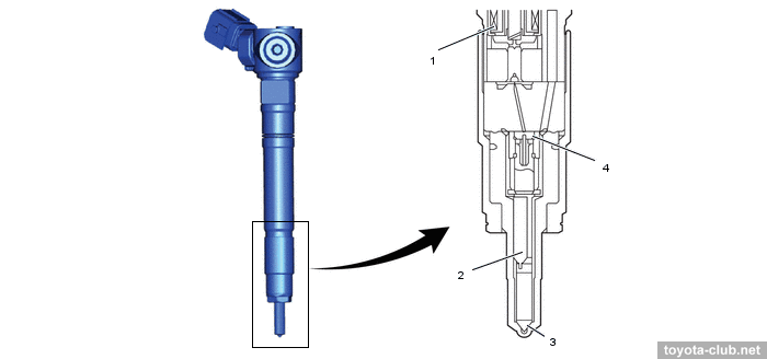
• The injectors are of the electromagnetic type. They use individual fuel pressure and temperature sensors, which allow to accurately adjust the injection volume of each injector, as well as to determine their malfunction (clogging or leaks). The injectors are equipped with built-in memory and a self-learning function.
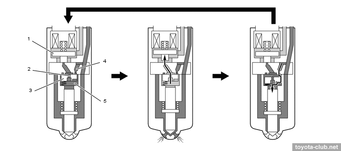
- When closed, the valve is held by a spring. The pressure in the control chamber is high. The fuel pressure acting on the bottom of the needle is not enough to open it.
- When the current supply to the coil, the valve opens the channel through which the fuel discharged from the control chamber. Due to pressure difference arises, the injector needle opens and fuel is injected.
- After current cut-off valve is closed. The control plate moves downward and fuel under high pressure fills control chamber and acts on top of the needle. The needle is closed and fuel injection stops. After pressure equalization in control chamber, the control plate is moved up by a spring.
1 - control valve, 2 - out-orifice, 3 - control plate, 4 - in-orifice, 5 - control chamber,
a - before injection, b - injection, c - after injection
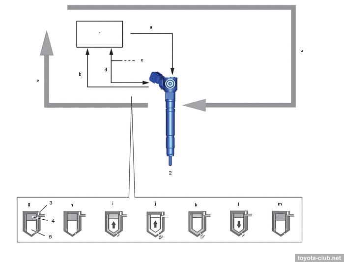
1 - ECM, 2 - injector (fuel pressure sensor, fuel temperature sensor, memory IC), 3 - fuel pressure sensor, 4 - control chamber, 5 - nozzle needle. a - operating signal, b - fuel pressure signal, c - each injector assembly, d - communication (fuel temperature signal and memory IC communication), e - feedback, f - command signal, g - no injection, h - electrical current starts to flow, i - injection starts, j - maximum injection rate has been reached, k - electrical current flow has stopped, l - injection rate has been reduced, m - injection has stopped
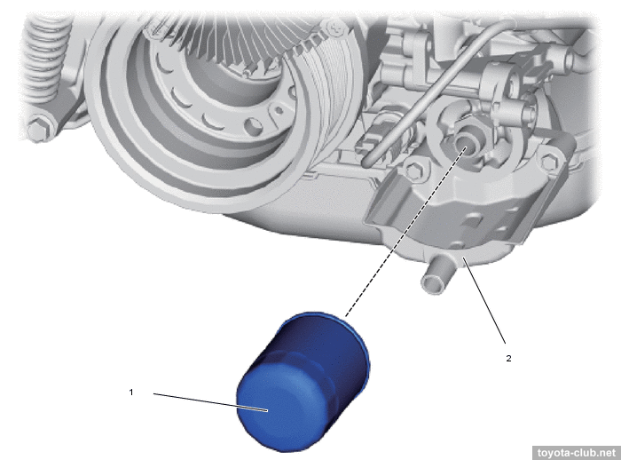
• Fuel filter - a rather complex design with the possibility of replacing the filter element.
• For models with two fuel tanks, an optional electric fuel pump is used.
• There are following sensors in the system:
- boost pressure
- crankshaft position (MRE-type)
- camshaft position (MRE-type)
- mass air flow (MAF) slot-in type, combined with intake air temperature sensor
- throttle position (Hall effect)
- accelerator pedal position (Hall effect)
- fuel pressure and temperature sensors built into the injectors
Emission control system
Depending on what environmental standards a particular vehicle complies with, the exhaust aftertreatment system can have varying degrees of complexity: EGR, EGR+DOC, EGR+DPF, EGR+SCR-DPF
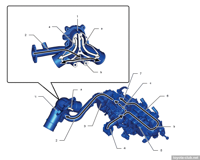
• EGR (exhaust gas recirculation) - bypass a part of exhaust gases to the intake to reduce the maximum temperature in the cylinder and reduce the nitrogen oxides emissions.
1 - intake pipe 1, 2 - EGR pipe 4, 3 - EGR control valve, 4 - EGR inlet, 5 - EGR cooler 1, 6 - EGR cooler 2, 7 - EGR valve #2. a - intake air, b - EGR gas, c - EGR gas (bypass)
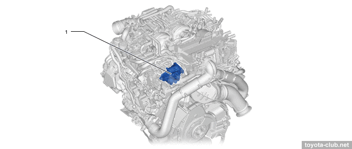
EGR valve - with a DC motor and Hall effect position sensor. The valve is located at the intersection of the inlet and EGR passages for even mixing of gases with air.
1 - EGR control valve
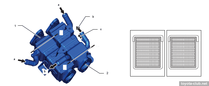
The recirculated gas temperature is reduced by two EGR coolers.
1 - EGR cooler 1, 2 - EGR cooler 2.
a - from cylinder head, b - to engine coolant pump, c - EGR valve #2
EGR valve # 2 (driven by a DC motor) optimizes the EGR gas temperature by controlling their passage through the coolers: in bypass mode, all flow is directed bypass the coolers, in cooling mode, vice versa.
A - bypass mode, B - mixed mode, C - cooler mode. 1 - EGR control valve, 2 - EGR gas temperature sensor, 3 - EGR valve #2, 4 - EGR cooler 1, 5 - EGR cooler 2.
a - to intake pipe 1, b - from cylinder head
Sensors are used:
- EGR temperature (downstream of EGR control valve)
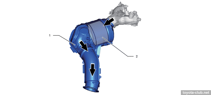
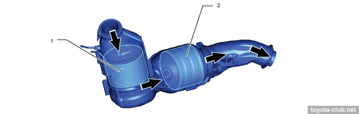
• DOC (oxidation catalyst) - primary stage of exhaust gas cleaning - oxidizes hydrocarbons and carbon monoxide to water and carbon dioxide.
• DPF (diesel particulate filter) - used to accumulation and combustion of soot particles, as well as CO+HC reducing.
1 - exhaust manifold converter, 2 - DPF
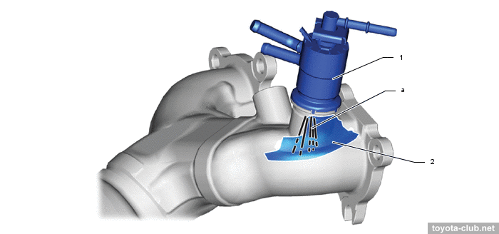
Additional low pressure fuel injector is built into the exhaust manifold, through which fuel is supplied directly from the pump to the exhaust to raise the DPF temperature and burn off accumulated soot particles. Inside the manifold, the jet of fuel collides with the mixer plate to mix more evenly with the exhaust gases.
Sensors are used:
- exhaust gas temperatures (before DOC, before DPF and after DPF)
- wide-range air-fuel ratio sensor (after DPF)
- differential pressure of DPF - allows to determine the grade of deposits
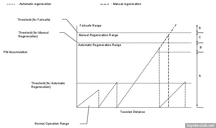
DPF passive regeneration can be performed by itself under the condition of exhaust gases high temperature (there is no need for control and supply of additional fuel).
The control unit constantly calculates the balance between the amount of accumulated and burnt soot, taking into account the condition of the engine, the rpms, the volume of fuel supply (by main and additional injectors). Depending on the received value, the unit decides whether automatic or manual regeneration is necessary and informs the driver.
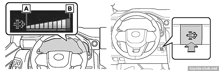
Display messages: A - "DPF Regeneration in Progress", B - "DPF Full See Owner's Manual", C - "DPF Full Manual Regeneration Required See Owner's Manual", D - "DPF Full Visit Your Dealer"
When regeneration is performed, the ECU activates the exhaust fuel injector and controls the fuel combustion in the engine. The DPF material temperature increases up to 600-700°C and soot particles burn out.
If the amount of accumulated soot exceeds the first threshold, the ECU performs automatic regeneration until the accumulation reaches zero.
If the amount of accumulated soot exceeds the second threshold, the ECU warns the driver to perform manual regeneration and displays the level of deposits. Manual regeneration can be started by DPR switch or using a diagnostic equipment.
If the amount of soot exceeds the permissible limit even in manual regeneration mode, it may cause the DPF damage. The ECU stops regeneration, activates emergency mode and warns the driver about a malfunction and the need to visit a workshop.
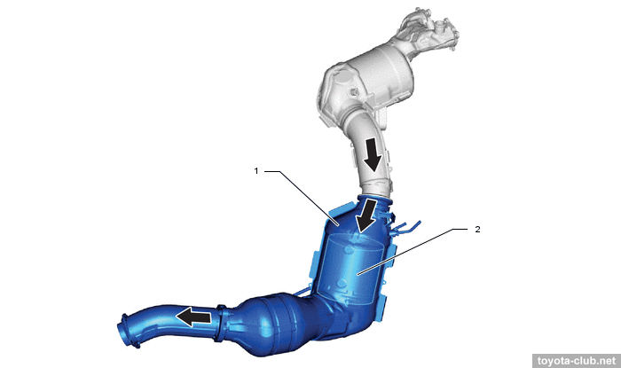
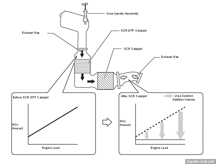
• SCR (selective catalytic reduction) - used to reduce of NOx contents in the exhaust gas by injection of urea solution (AdBlue/DEF). The SCR-DPF catalyst also performs a particulate cleaning function.
1 - SCR-DPF catalyst, 2 - SCR catalyst
After injection of the solution the water vaporizes, then urea dissociates into isocyanic acid and ammonia by hydrolysis. At high temperature the isocyanic acid in its turn dissociates to carbon dioxide and ammonia by hydrolysis. Ammonia accumulates in the catalyst and reacts with nitrogen oxides of exhaust gases, resulting in a pure nitrogen and water.
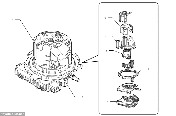
The urea solution is supplied by a multifunctional module in the lower part of the AdBlue tank. The pump delivers the solution under a pressure of about 500 kPa to the urea injector (feedback is carried out by a pressure sensor). The heater maintains the liquid state of the solution at negative temperatures (feedback is carried out by the temperature sensor in the pump). The presence of urea itself in the solution is monitored by a concentration sensor. A filter and a solution level sensor are provided.
Sensors are used:
- exhaust gas temperature (after SCR catalyst)
- NOx 1 (in the exhaust manifold) - measures the concentration of NOx and oxygen
- NOx 2 (in the exhaust pipe) - measures the concentration of NOx
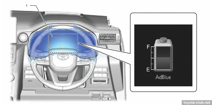
The AdBlue consumption, which is proportional to the NOx content in the exhaust gases, depends primarily on the engine load. The average consumption is declared 1 liter per 1000 km of mileage, the maximum - about 2 ltrs (considering that for heavy trucks the consumption of urea is about 5% of the fuel consumption - here the figures look very modest). The volume of the urea tank is 17.4 liters. When the remaining AdBlue is enough for 2400 km mileage, the low level indicator turns on; when the remains enough for 1100 km, a warning about engine start appears. When AdBlue is completely depleted, the engine runs, but cannot be restarted, and requires to top up at least 7 liters of fluid.
1 - multi-information display
Experience
• Impossible to complete DPF regeneration due to fuel addition injector failure. Described in TSB EG-00743T-TME (28.04.2022)
• Jerking and strange sound from turbocharger during accelerating. Described in TSB EG-00770T-TME (30.06.2022, upd. 26.09.2022)