|
Eugenio,77
mail@toyota-club.net
© Toyota-Club.Net
Aug-Sep 2021
LC200'07 Euro-2..4 ·
LC200'12 Euro-5 ·
LC70'07 ·
Experience
Describing the structure of the new diesel engine, it would be correct to pay attention to its nominal predecessor. Here we will talk about the technical features, the differences between versions and generations, and in conclusion we will list and illustrate the common problems known from practice.
Specifications
| Engine | Displacement, cm3 | Bore x Stroke, mm | Compression ratio | Output, PS | Torque, Nm | - |
| 1VD-FTV | 4461 | 86.0 x 96.0 | 16.8 |
272 / 3600 | 650 / 1600-2800 | E-V |
285 / 3600 | 650 / 1600-2800 | E-IV |
265 / 3400 | 650 / 1600-2600 | Aus,Euro |
235 / 3200 | 615 / 1800-2200 | Gen, IC AT |
220 / 3600 | 430 / 1200-3600 | Gen, IC MT |
185 / 3200 | 430 / 1600-3000 | Gen, MT |
205 / 3400 | 430 / 1200-3200 | LC70, E-IV |
Engine weight: 320-360 kg.
Emissions grades: Euro 0-2-3-4-5
Application: Land Cruiser J200, Land Cruiser J70, Lexus LX450
Engine mechanical
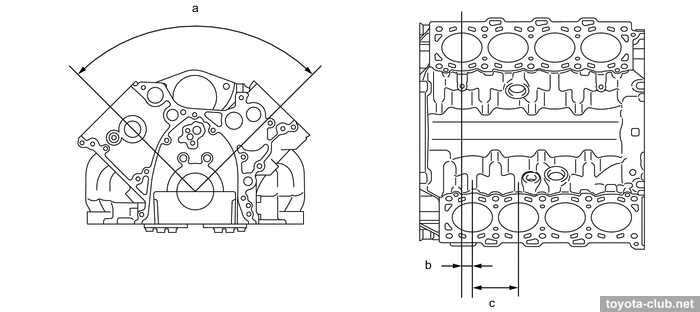
Cast iron (CGI - compact graphite iron) cylinder block with a bank angle of 90° and a closed deck.
|
a - 90°, b - 22 mm, c - 97 mm
|
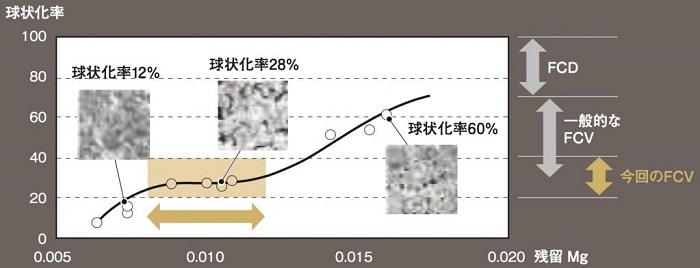
VD engine uses FCV (vermicular graphite cast iron) for the block, that has a tensile strength of 350 to 500 MPa. To keep the spheroidization rate of graphite within range of 20-40%, the residual amount of Mg is severely controlled, and cerium is added to suppress the evaporation of Mg in the molten metal.
FCV is rather difficult to cast and has poor workability, but it was overcome by casting dimensional accuracy, and the cutting speed suppression to extend the life of the cutting tool.
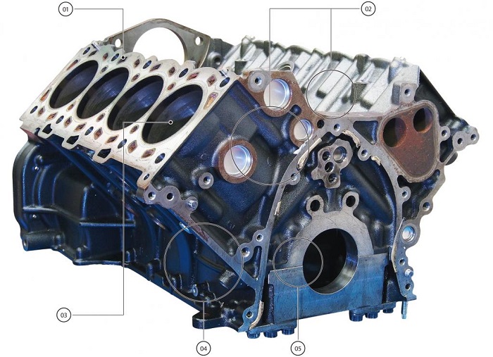
01 - Head surface: the graphite spheroidization rate is 25%, hardness is 230HV.
02 - Thin and rib structure: cooling channel is only located at part where the piston reciprocates; the wall thickness was reduced to the limit and the ribs were added; since these parts are hardened at the end in gravity casting, porosity is likely to occur.
03 - Cylinder inner wall integrated type without liners: the same hardness as at head surface
04 - Side rib structure: the outer wall surface is designed by combining the outer wall of the cooling channel with the rib structure.
05 - Reduced machining length: side bolt type structure was rejected in favor of bottom fastening type for suppressing the processing length.
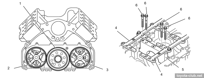
The main bearing caps are separate, but connected to each other and to the block with stiffeners. There are driven gears of oil pump and scavenging pump at the rear of the block.
|
1 - oil pump drive gear, 2 - scavenging pump, 3 - oil pump, 4 - stiffener, 5 - crankshaft bearing cap, 6 - bolts
|
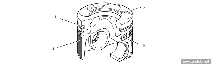
Pistons - aluminum, with a combustion chamber and a cooling channel. The groove of the upper compression ring is made in the ni-resist insert. The skirt has a resin coating. Top ring lip has anti-wear PVD coating (for emerging markets).
|
1 - top ring groove (ni-resist cast iron ring carrier). a - resin coating, b - cooling channel, c - combustion chamber
|
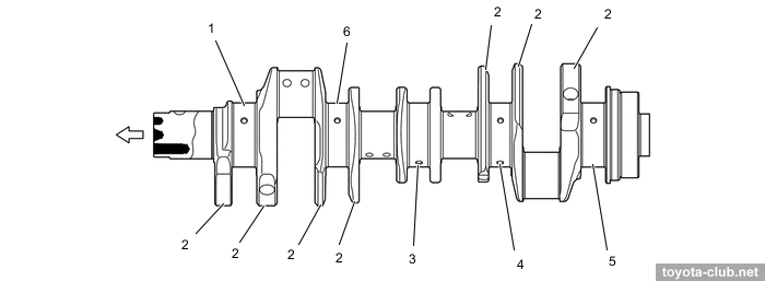
The crankshaft is forged steel, with 5 journals and 7 counterweights.
|
1 - journal 1, 2 - balance weight, 3 - journal 3, 4 - journal 4, 5 - journal 5, 6 - journal 2
|
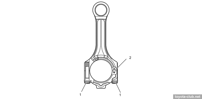
Connecting rods are made of high-strength steel, with knock pins for fixing the caps.
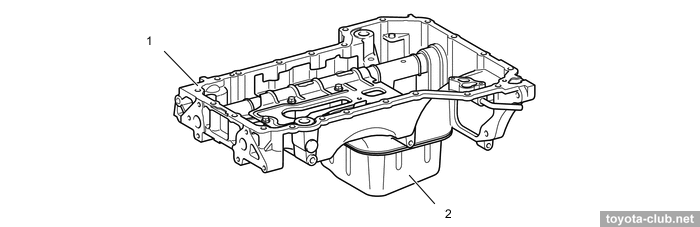
The oil sump consists of a upper aluminum part and a steel sump.
|
1 - oil pan 1, 2 - oil pan 2
|
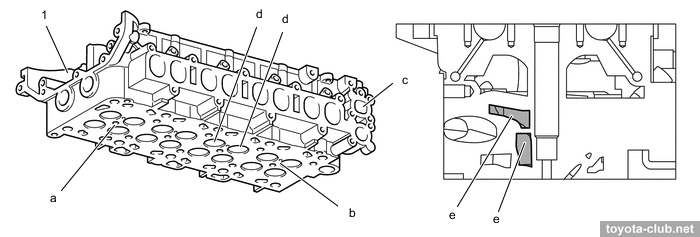
Cylinder head - aluminum, with a two-level cooling jacket. EGR channel passes through the head, allowing additional cooling of the gases.
|
1 - cylinder head. a - injector hole, b - glow plug hole, c - EGR passage, d - intake ports, e - two-stage water jacket
|
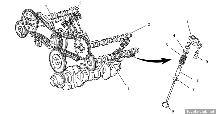
Valve mechanism - DOHC 32V: double camshafts in the heads and four valves per cylinder. There are valve adjusters and roller rockers in the valve mechanism.
|
1 - exhaust camshaft, 2 - intake camshaft, 3 - valve rocker arm, 4 - valve spring retainer, 5 - compression spring, 6 - valve, 7 - valve spring seat, 8 - valve guide bush, 9 - valve lash adjuster
|
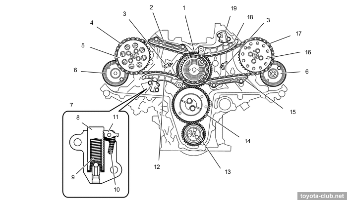
Valvetrain is "three-step" - from the crankshaft to injection pump shaft by gears, then by secondary chains (pitch 9.525 mm) to intake camshafts, and by gears to exhaust camshafts. The chain tension is maintained by hydraulic tensioners with additional springs and a ratchet. Idler and camshaft gears - scissors type.
|
1 - supply pump drive gear, 2 - chain vibration damper 1, 3 - oil jet, 4 - timing chain 1, 5 - camshaft timing sprocket 1, 6 - cam gear, 7 - chain tensioner 1, 8 - plunger, 9 - spring, 10 - cam spring, 11 - cam, 12 - chain tensioner slipper 1, 13 - crankshaft timing gear, 14 - idle gear 1, 15 - chain vibration damper 2, 16 - camshaft timing sprocket 2, 17 - timing chain 2, 18 - chain tensioner slipper 2, 19 - chain tensioner 2
|
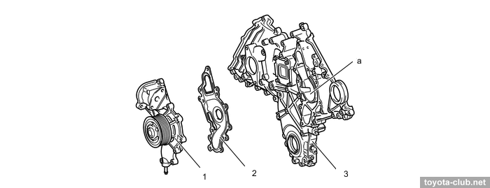
A coolant pump is built into the timing chain cover.
|
1 - coolant pump, 2 - gasket, 3 - timing chain cover. a - swirl chamber
|
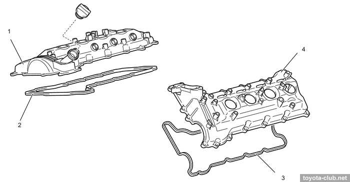
The cylinder head covers are made of plastic.
|
1/4 - cylinder head cover, 2/3 - gasket
|
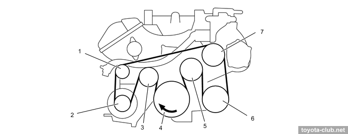
Auxiliaries are driven by common belt with automatic tensioner. The version with a viscous heater received another belt and a whole pack of idler rollers.
|
1 - idler pulley, 2 - generator, 3 - tensioner, 4 - crankshaft, 5 - fan pulley, 6 - A/C compressor, 7 - coolant pump
|
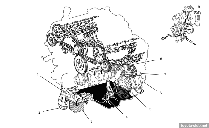
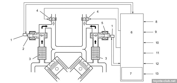
Lubrication
|
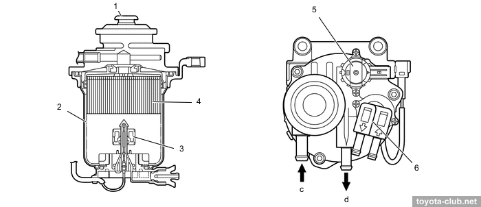
1 - filter bracket, 2 - oil filter, 3 - oil cooler, 4 - oil strainer, 5 - oil catch tank, 6 - turbocharger #2, 7 - scavenging pump, 8 - oil pump, 9 - turbocharger #1
|
The trochoid type oil pump is driven by a gear from the crankshaft.
Oil cooler is installed on the filter bracket.
The oil nozzles with check valves are installed to cylinder block for cooling and lubrication of pistons.
|
1- oilz nozzle, 2 - check valve
|
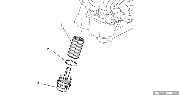
Collapsible type oil filter with plastic housing.
|
1 - oil filter element, 2 - o-ring. a - oil filter cap
|
The scavenging pump is designed to drain oil from the turbochargers when driving on a slope. Oil is taken from a catching tank (where liquid and gaseous fractions are separated) and discharged into a sump.
|
1 - scavenging pump, 2 - turbocharger #2, 3 - oil catch tank, 4 - turbocharger #1 |
|
1 - scavenging pump, 2 - oil pump gear, 3 - oil catch tank, 4 - turbocharger, 5 - oil pan
|
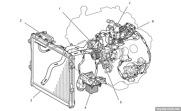
Cooling
Cooling system of classical design, mechanical "cold" thermostat (74-78°C), mechanical belt driven pump.
|
1 - thermostat, 2 - radiator reservoir tank, 3 - radiator, 4 - oil cooler, 5 - coolant pump, 6 - EGR cooler, 7 - EGR pipe #3
|
Intake and exhaust
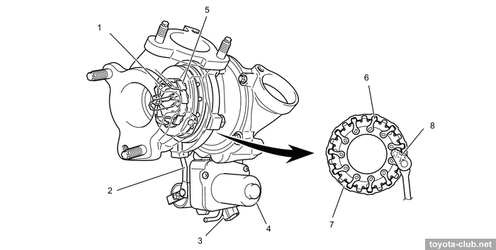
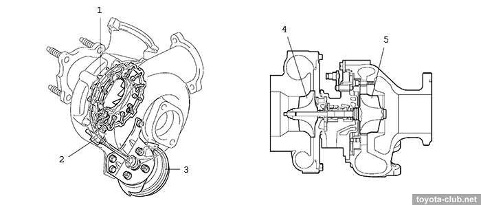
A pair of turbochargers with variable geometry (VGT or VNT) operate separately for each bank. VGT of 2nd generation (electric actuator), controlled via driver unit.
The variable geometry of the vanes allows to maintain an optimal boost pressure in a wide range of engine speed, reduce back pressure at high speeds, and increase power at low speeds.
|
1 - turbine wheel, 2 - linkage, 3 - nozzle vane position sensor, 4 - DC motor, 5 - nozzle vane, 6 - driven arm, 7 - unison ring, 8 - drive arm
|
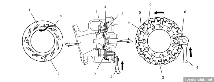
- At low load or low engine speed actuator moves the control ring and turns pivotally connected vanes to partially closed position. This increases the speed of gas entering the turbine, increases the boost pressure and increases engine torque.
1 - nozzle vane, 2 - plate, 3 - unison ring, 4 - linkage, 5 - driven arm, 6 - drive arm.
a - gas flow, b - cutout portion, c - fulcrum
|
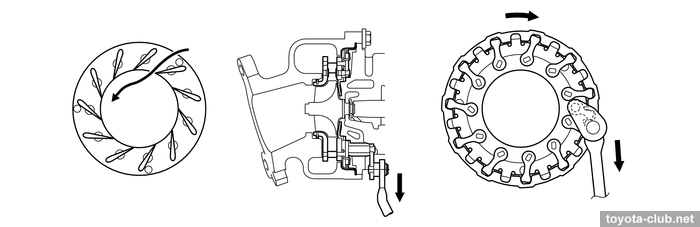
- At high load or med-to-high speed vanes are moved to the open position, allowing maintain the desired boost pressure and reduce resistance at exhaust.
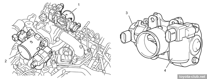
Throttle valves are installed in the intake, with an electric drive (rotary solenoid) and a non-contact position sensor.
|
1 - throttle (B2), 2 - throttle (B1), 3 - throttle position sensor, 4 - throttle control motor
|
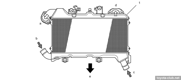
To cool the charge air car is equipped with intercooler.
|
1 - intercooler. a - to throttle (B1), b - from turbocharger #1, c - from turbocharger #2, d - to throttle (B2)
|
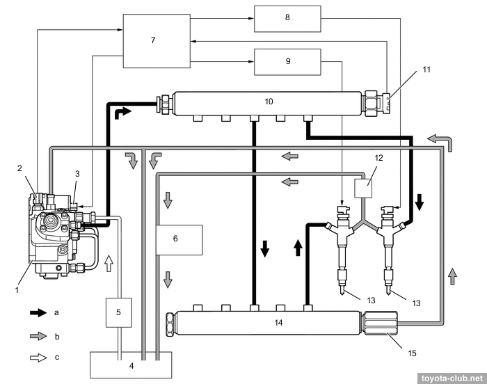
Fuel system / Engine control
Common Rail type fuel system - the fuel is supplied by high pressure pump in a common rail and then is injected into the cylinders via the electronically controlled injectors. The injection pressure - 25-175 MPa (Euro-4), 25-129 MPa (Euro-0..3)
|
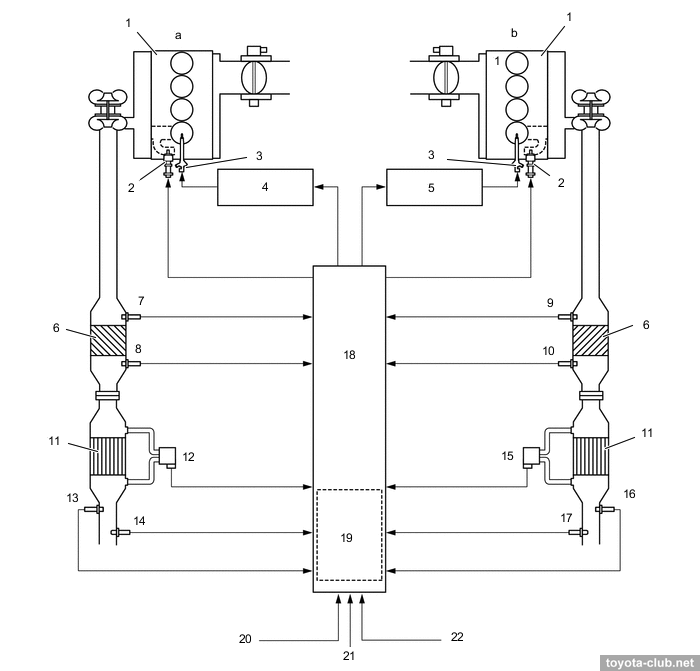
1 - injection pump, 2 - fuel temperature sensor, 3 - SCV, 4 - fuel tank, 5 - fuel filter, 6 - fuel cooler (air type), 7 - ECM, 8 - injector driver 1, 9 - injector driver 2, 10 - common-rail LH, 11 - fuel pressure sensor, 12 - fuel cooler (water type), 13 - injector, 14 - common-rail LH, 15 - pressure limiter. a - high pressure fuel, b - return fuel, c - suctioned fuel
|
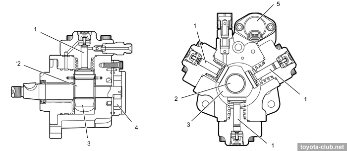
Injection pump - HP4 type, 3-plunger. Fuel pressure is controlled by metering the fuel supply at the injection pump inlet.
|
1 - plunger, 2 - inner cam, 3 - outer cam, 4 - feed pump, 5 - SCV
|
Under the action of a rotating inner eccentric cam, an outer cam pushes one of the plungers, pumping fuel into the rail, while a spring pushes the other plunger, which sucks fuel into the injection pump chamber.
|
1 - SCV valve, 2 - plunger A, 3 - plunger B, 4 - plunger C, 5 - outer cam, 6 - inner cam.
a - suction, b - to injector, c - pumping finish, d - pumping start, e - suction
|
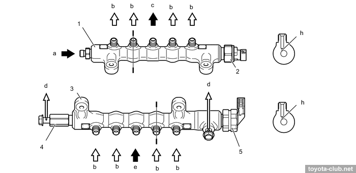
A fuel pressure sensor and a mechanical pressure relief valve are installed in the fuel rail.
|
1 - common-rail RH, 2 - fuel pressure sensor, 3 - common-rail LH, 4 - pressure limiter. a - from injection pump, b - to injector, c - to common-rail LH, d - to fuel tank, e - from common-rail LH, h - branch hole
|
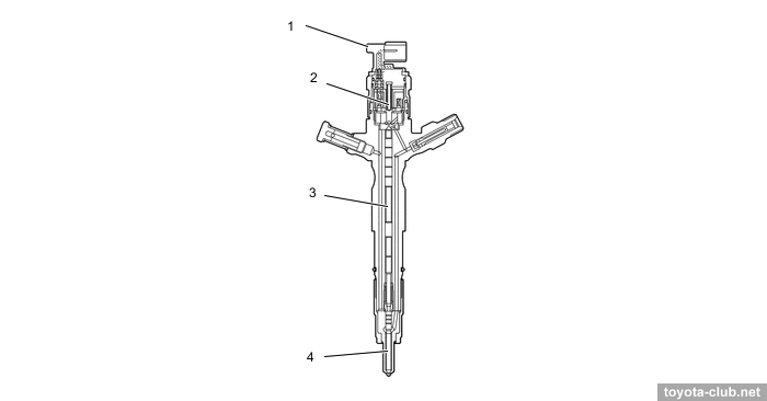
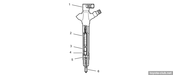
The injectors are of the electromagnetic type.
|
1 - injector, 2 - solenoid valve, 3 - piston, 4 - nozzle needle
|
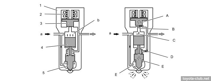
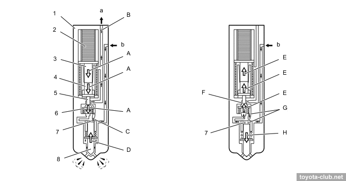
- When closed, the valve is held by a spring, and the fuel pressure in the control chamber holds the piston in the bottom position, which in turn locks the needle in the closed position (the fuel pressure acting on the bottom of the needle is not enough to open it).
- When the current supply to the coil, the valve opens the channel (A), through which fuel flows to the bottom of the piston (B). This reduces the pressure in the control chamber (C) and the pressure increases below the piston, whereby piston moves up (D). Simultaneously the needle opens and fuel injection occurs (E).
- After current cut-off valve is closed by the spring. At this point, the pressure in the control chamber increases, the piston moves down, the needle closes and injection is terminated.
|
1 - injector, 2 - solenoid coil, 3 - solenoid valve, 4 - piston, 5 - nozzle needle. a - fuel, b - control chamber
|
Fuel filter - with replaceable filter element, vacuum switch, sedimenter level warning switch and recirculation heater with bimetallic valve.
|
1 - priming pump, 2 - fuel filter case, 3 - fuel sedimenter level warning switch, 4 - fuel filter element, 5 - fuel filter warning switch, 6 - fuel heater. c - from fuel tank, d - to injection pump
|
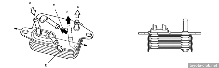
Air-type and liquid-type coolers are installed in the return line to cool the fuel.
|
Liquid-type cooler. 1 - fuel cooler. a - fuel (from left bank), b - fuel (from right bank), c - fuel (to fuel tank), d - water out, e - water in
|
For models with two fuel tanks, an optional electric fuel pump is used.
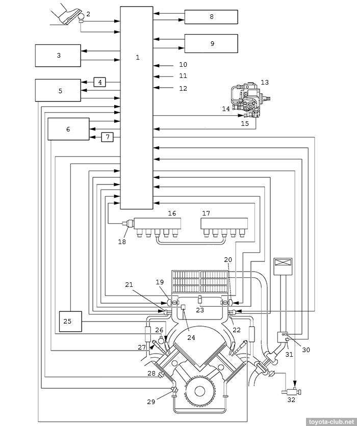
There are following sensors in the system:
- mass air flow (MAF)
- atmospheric pressure
- fuel pressure
- intake manifold absolute pressure
- crankshaft position (inductive)
- camshaft positions (inductive)
- throttle position (non-contact)
- accelerator pedal position (non-contact)
- coolant temperature
- intake air temperature
- fuel temperature
The function of engine oil condition monitoring (Oil Maintenance Management System) provided:
ECU calculates the theoretical oil condition (soot content) based on the engine operating conditions and displays the message "Oil Maintenance Reqd". The maximum interval before replacement in this case is 30000 km or 2 years.
DTC codes of 1VD-FTV
Emission control system
EGR (exhaust gas recirculation) - bypass a part of exhaust gases to the intake to reduce the maximum temperature in the cylinder and reduce the nitrogen oxides emissions.
|
1 - EGR valve position sensor, 2 - EGR valve 1, 3 - EGR cooler, 4 - throttle motor,
5 - EGR valve 2, 6 - ECM, 7 - atmospheric pressure sensor, 8 - accelerator pedal sensor, 9 - crank position sensor, 10 - mass air flow meter, 11 - coolant temperature sensor, 12 - atmospheric temperature sensor, 13 - manifold absolute pressure sensor
|
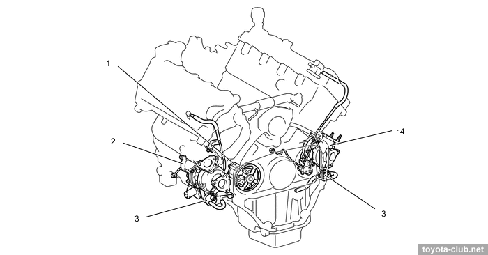
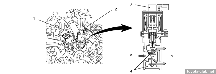
EGR valves - linear solenoid type, with position sensor.
|
1 - EGR valve 1, 2 - EGR valve 2, 3 - EGR valve position sensor, 4 - dual-valve. a - exhaust gas in (from exhaust manifold), b - exhaust gas out (to intake manifold)
|
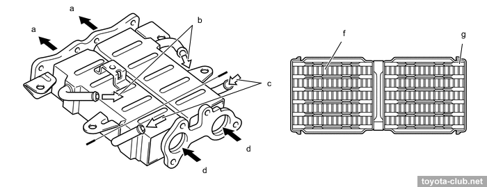
The recirculated gas temperature is reduced by a dual EGR cooler.
|
a - exhaust gas (to EGR valve), b - coolant out, c - coolant in, d - exhaust gas (from cylinder head). f - exhaust gas, g - coolant
|
DOC (oxidation catalyst) - primary stage of exhaust gas cleaning - oxidizes hydrocarbons and carbon monoxide to water and carbon dioxide. Euro-2..3 versions - 2 catalysts are installed in the exhaust, Euro-4 version - 4 catalysts.
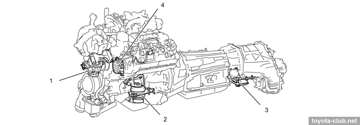
Engine mounts
The powertrain is suspended with three mountings, the front ones are of hydraulic active type.
|
1/2 - front engine mounting insulator, 3 - rear engine mounting insulator, 4 - vacuum pump
|
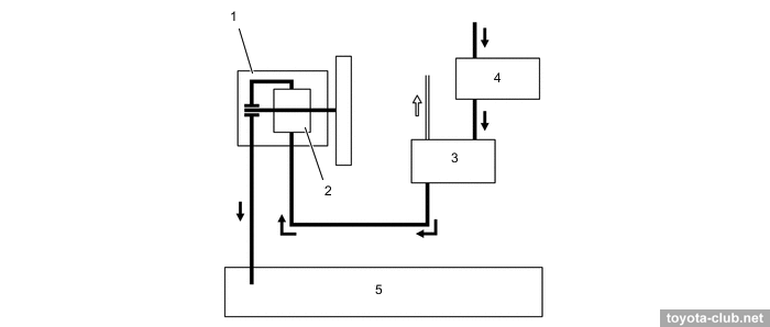
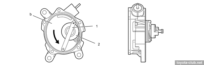
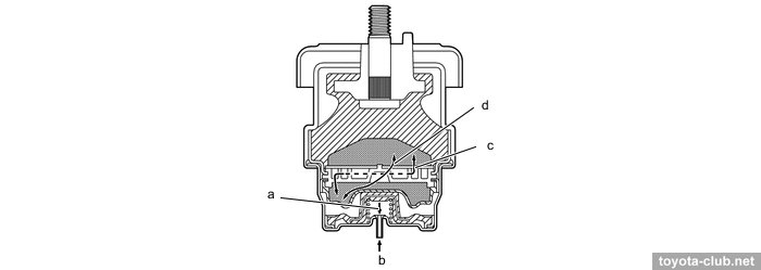
A vacuum pump was required to operate the mountings.
|
1 - vane, 2 - rotor. b - pump chamber
|
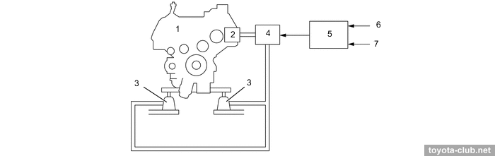
|
1 - engine, 2 - vacuum pump, 3 - mounting, 4 - VSV, 5 - ECM, 6 - vehicle speed signal, 7 - crank position sensor
|
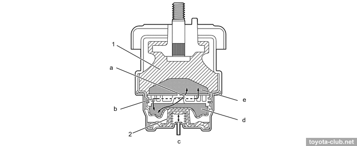
The vacuum is supplied to the mounting via VSV, the diaphragm opens or closes the channel connecting the fluid chambers 1 and 2. Channel 1 connects the chambers constantly, regardless of the position of the diaphragm. Channel 2 connects chambers only when the diaphragm is open.
|
1 - rubber, 2 - diaphragm, a - fluid passage 2, b - fluid passage 1, c - vacuum intake, d - fluid chamber 2, e - fluid chamber 1, f - fluid
|
- When the engine is running at low rpms and low vehicle speed, the VSV is on, a vacuum from the vacuum pump is supplied to the diaphragm, which opens channel 2 for free flow of fluid inside the mounting. This allows vibration from the engine to be damped more "gently".
|
a - diaphragm descends, b - vacuum introduced, c - fluid passage 1, d - fluid passage 2
|
- With an increase in rpms and/or speed, the ECM shuts off the VSV, stopping the vacuum supply to the diaphragm. So there is only one channel with a relatively high resistance between the chambers.
|
a - no vacuum, b - diaphragm stopped, c - fluid passage 1
|
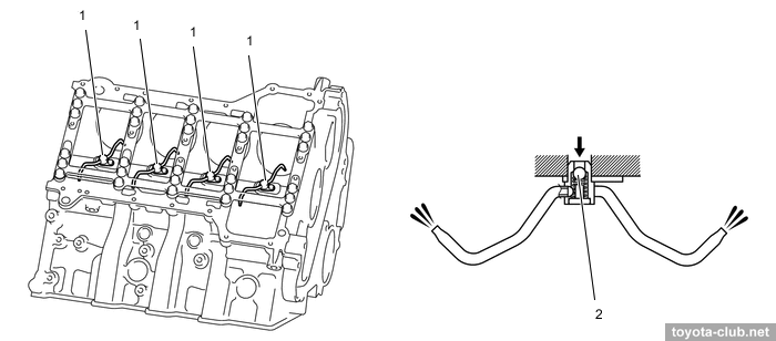
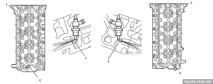
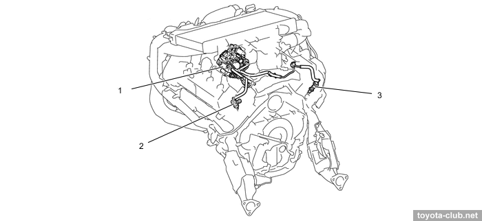
• The cylinder head provides space for the exhaust fuel injectors.
|
1 - cylinder head. a - B2, b - B1, c - exhaust fuel injector hole, e - to exhaust port, f - injection passage
|
• VGT turbochargers are controlled directly by ECU.
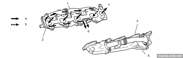
• The exhaust manifolds of a new configuration.
|
1 - exhaust manifold pipe #1, 2 - exhaust manifold (B1), 3 - exhaust manifold (B2), 4 - exhaust manifold pipe #2. a - exhaust gas, b - exhaust gas and fuel, c - to EGR valve
|
• The injection pressure in the Common Rail system is up to 200 MPa.
|
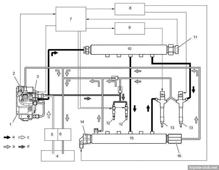
1 - injection pump, 2 - fuel temperature sensor, 3 - SCV, 4 - fuel tank,
5 - fuel filter, 6 - fuel heater, 7 - ECM, 8 - injector driver 1, 9 - injector driver 2, 10 - common-rail RH, 11 - fuel pressure sensor, 12 - exhaust fuel injector, 13 - injector, 14 - fuel pressure discharge valve, 15 - common-rail LH, 16 - pressure limiter. a - high pressure fuel, b - return fuel, c - suctioned fuel, d - fuel to exhaust fuel injector
|
• Fuel pressure is controlled by metering the fuel supply at the injection pump inlet and metering the drain through the pressure discharge valve.
• There are fuel pressure sensor and pressure discharge valve in the fuel rail. Electronically controlled valve opens and closes by a signal from the control unit, moreover, it can function of emergency pressure relief.
|
1 - common-rail RH, 2 - fuel pressure sensor, 3 - common-rail LH, 4 - pressure limiter, 5 - fuel pressure discharge valve. a - from supply pump, b - to injector, c - to common-rail LH, d - to fuel tank, e - from common-rail RH, h - branch hole
|
• Injectors - piezoelectric type.
|
1 - injector, 2 - piezo actuator, 3 - piston 1, 4 - piston 2, 5 - three-way valve, 6 - nozzle needle
|
- When voltage is applied to the piezoelectric element its linear dimension changes, pistons and valve move downward (A). Overlapped by top of the valve drain channel from control chamber opens (B). Pressure in the control chamber drops (C). The needle moves up and fuel injection occurs (D).
- After current cut-off the pistons and valve returns by springs (E). Drain channel is closed (F). The pressure in the control chamber increases (G). The needle moves down and fuel injection stops (H).
|
1 - injector, 2 - piezo actuator, 3 - piston 1, 4 - piston 2, 5 - orifice, 6 - three-way valve, 7 - control chamber, 8 - nozzle needle. a - return fuel, b - fuel from common-rail
|
• Added to the control system:
- particulate filter differential pressure sensors
- exhaust gas temperature sensors
- air-fuel ratio sensors (B1S1/B2S1)
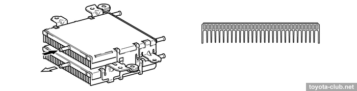
• DPF (diesel particulate filter) - used to accumulation and combustion of soot particles.
|
1 - cylinder head, 2 - exhaust fuel injector, 3 - injector, 4 - injector driver #2, 5 - injector driver #1, 6 - oxidation catalyst, 7 - exhaust gas temperature sensor (B2S1), 8 - exhaust gas temperature sensor (B2S2), 9 - exhaust gas temperature sensor (B1S1), 10 - exhaust gas temperature sensor (B1S2), 11 - DPF, 12 - differential pressure sensor (B2), 13 - exhaust gas temperature sensor (B2S3), 14 - air-fuel ratio sensor (B2), 15 - differential pressure sensor (B1), 16 - exhaust gas temperature sensor (B1S3), 17 - air-fuel ratio sensor (B1), 18 - ECM, 19 - atmospheric pressure sensor, 20 - mass air flow meter, 21 - DPF switch, 22 - engine coolant temperature sensor.
|
Additional low pressure fuel injectors are built into the exhaust, through which fuel is supplied directly from the pump to the exhaust to raise the DPF temperature and burn off accumulated soot particles.
|
1 - injection pump, 2/3 - exhaust fuel injector
|
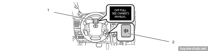
DPF passive regeneration can be performed by itself under the condition of exhaust gases high temperature (there is no need for control and supply of additional fuel).
The control unit constantly calculates the balance between the amount of accumulated and burnt soot. Depending on the received value, the unit decides if regeneration is necessary and informs the driver. Manual regeneration can be started by DPR switch. When regeneration is performed, the ECU activates the exhaust fuel injector and controls the fuel combustion in the engine. The DPF material temperature increases up to 600-700°C and soot particles burn out.
If the amount of soot exceeds the upper permissible limit, ECU activates emergency mode and warns the driver about the need to visit the service (to replace the DPF).
|
1 - multi-information display, 2 - DPR switch
|
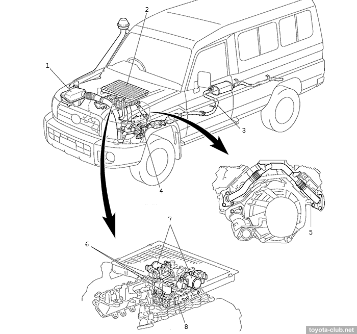
The version for Land Cruiser 70 family appeared six months earlier than LC200 engines. Its most notable difference is a single turbocharger.
|
1 - air filter, 2 - intercooler, 3 - exhaust pipe, 4 - turbocharger, 5 - crossover pipe, 6 - EGR valve, 7 - throttle body, 8 - EGR cooler
|
• The fuel system is similar to LC200'07. The injection pressure for the Euro-4 version is 25-157 MPa.
|
1 - ECM, 2 - accelerator pedal position sensor, 3 - diagnostic connector, 4 - EDU relay 2, 5 - EDU 2, 6 - EDU 1, 7 - EDU relay 1, 8 - main relay, 9 - transponder, 10 - ignition switch, 11 - stop lamp switch, 12 - alternator, 13 - injection pump, 14 - SCV, 15 - fuel temperature sensor, 16 - common rail RH, 17 - common rail LH, 18 - fuel pressure sensor, 19 - throttle 1, 20 - throttle 2, 21 - EGR valve 1, 22 - EGR valve 2, 23 - intake air temperature sensor, 24 - boost pressure sensor, 25 - glow relay, 26 - camshaft position sensor, 27 - injector, 28 - coolant temperature sensor, 29 - crankshaft position sensor, 30 - ambient temperature sensor, 31 - air flow meter, 32 - E-VRV.
|
• VGT of 2nd generation (vacuum actuator).
|
1 - nozzle vane, 2 - linkage, 3 - actuator, 4 - impeller wheel, 5 - turbine wheel
|
- At low load or low engine speed.
|
- At high load or high engine speed.
|
In the national auto repair community, 1VD-FTV has well-deserved respect: large amount of repair times, moderate requirements for the techician qualification, the absence of normal seconda-hand engines, a well-known list of standard malfunctions, a large number of clients - in combination with surprisingly low durability, all this made it a stable source of income for many workshops.
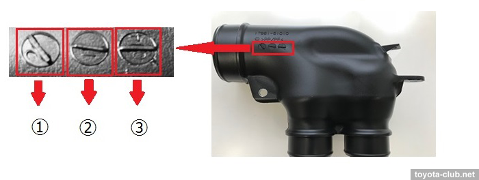
• It's worth to start with a very interesting, but for some reason not very widespread bulletin: TSB EG-00130T-TME "Knocking noise caused by cylinder bore abnormal wear due to dust ingress" (v.2, 06/26/2019).
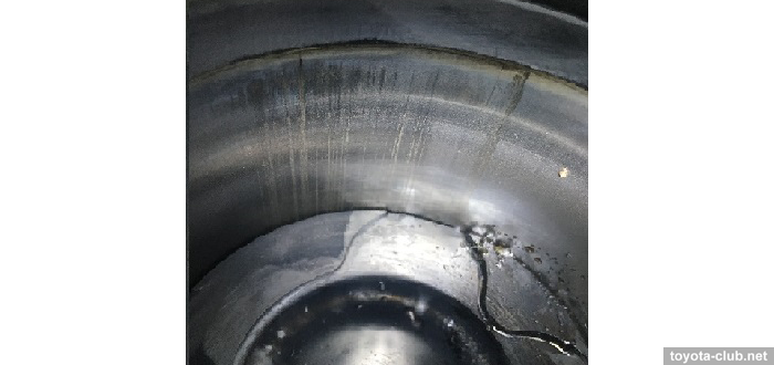
The problem is engine knocking sound caused by abnormal cylinder wear due to dust ingress to the intake system.
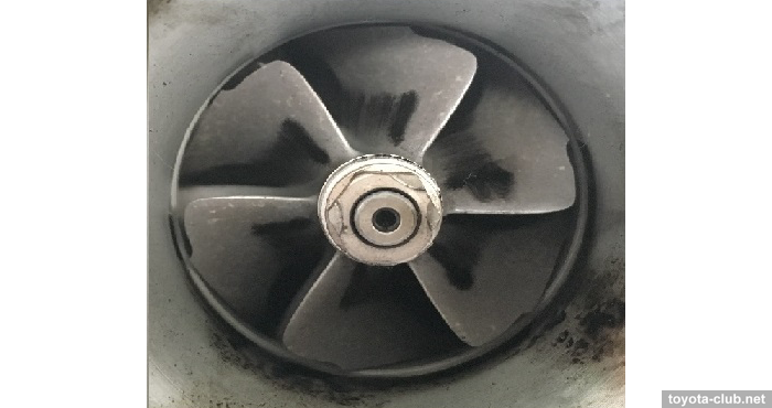
The second symptom is wear of the compressor impeller (accompanied by a power drop, white smoke at exhaust, increased oil consumption).
A possible cause is a dust ingress in the intake due to burr of the air connector 17861-51010.
Changes - in September 2018 only, an operation to remove burr was added to the production process, the part number did not change. Prescription - replace the connector with one released after the date of change, carry out repairs in accordance with the manual, replace the turbocharger if necessary.
It is not possible to assert whether such a trifle could lead to such global consequences, or the Japanese traditionally try to cover up more serious and costly mistakes, but this, to some extent, explains so usual for 1VD-FTV phenomenon of early and often repeated wear of the cylinders nd turbines.
It has been known for a long time about dirty air at the inlet, but the causes are considered to be either crankcase ventilation, or cheap air filters and their untimely replacement, or simply the inability to clean too much air flow. In the case of Toyota, manufacturing defects are the last thing to think about (seemingly).
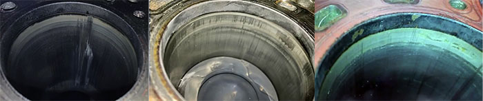
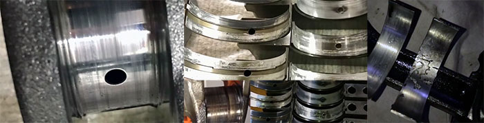
• The canonical cause of wear (with an impressive step near TDC zone) and scoring in the cylinders is considered to be abundant carbon deposits in the groove of the upper compression ring, which seems to push the ring out of the groove. The technicians with extensive experience in VD repairs have questions about the quality of cylinder block material.
In addition, the piston can surprise with the ring wear and its widened groove.
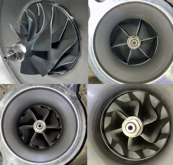
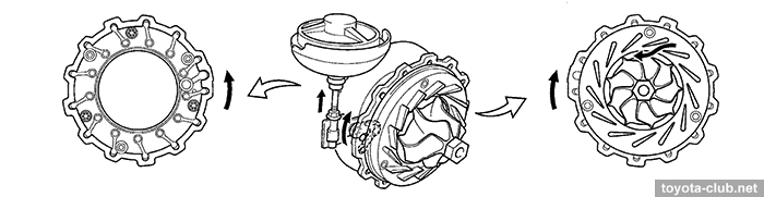
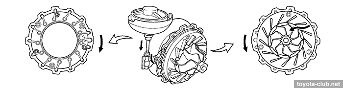
• The life cycle of a left compressor of 1VD-FTV can be illustrated as follows:
Although the extreme backlash of the shaft and the oil stream in the outlet pipe can force to perform repair before the last stage of the impeller wear.
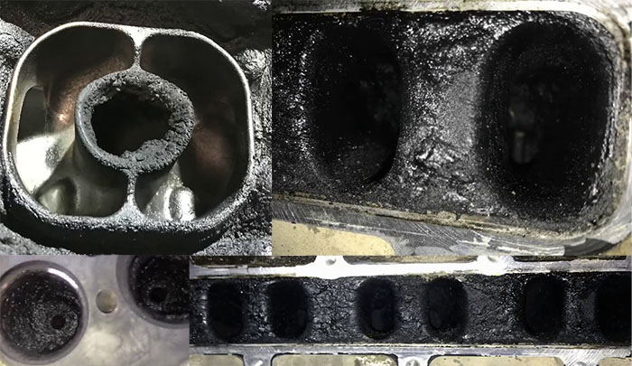
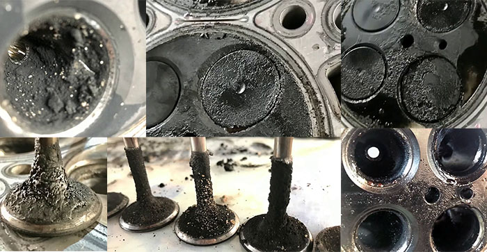
• Practice has confirmed that EGR is the main cause of appearance and spread of carbon deposits. In this engine, the flow of recirculating gases is large and, together with the oil from the crankcase ventilation, gives (in the left half of the engine) a synergistic effect of contamination the intake tract and the combustion chamber and the exhaust. There is also an uneven distribution of soot over the cylinders. An imperfect combustion process or an excess of oil in the crankcase gases make the development of the process an avalanche. In any case, the EGR system of 1VD-FTV engines can and should be shut-off.
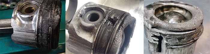
• Scratched crankshaft, worn out and displaced bearings, blue (overheated) connecting rods - in each individual case, it is easiest way to consider operation without oil as cause. However, when analyzing the array of such problems and related circumstances, this explanation is no longer enough.
• Moderate (up to 300 ml / 1000 km) and non-progressive oil consumption was not considered a problem even for new engines, consumption up to 100 ml did not deserve mention at all. But with higher rates of oil burn, should not really expect to simply feed the engine with another quart of oil for as long as like.
• The best oil change interval for 1VD-FTV is still 5000 km. Increasing it to 10000 from a technical point of view was unjustified, the European 15000 are already beyond reasonable, but the operation according to OMMS, theoretically allowing an interval of 30000, is just the destruction of the engine, regardless of the quality of the diesel fuel used.
• The vacuum pump, especially in the first years of production, was the main cause of the unexplained oil consumption. In this case, the installation of the modernized pump (and its regular replacement) was enough.
• If the condition of the cylinders and pistons requires to disassemble the engine, then with a high probability in the removed cylinder heads there will be intake valves covered with abundant carbon deposits with worned edges, destroyed valve seats and oval holes in the guide bushings. And the masters talk about the unbeliveable rate of wear again.
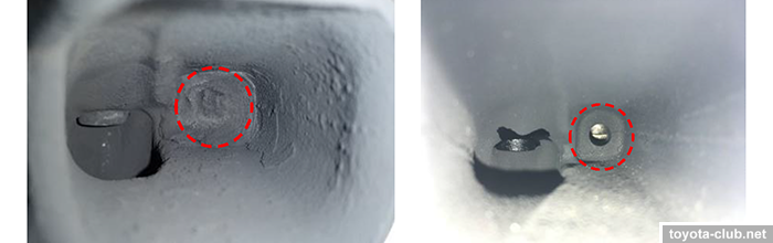
• Degradation of the springs of the oil nozzle check valves, which do not prevent the oil from draining at an already low pressure, is noted.
• A small sketch regarding deposits - TSB EG-0144T-1114 "P2458,2463 due to clogged LH bank additional fuel injector port" (31.08.2017). Since 07.2014, the design of the cylinder head has been changed, since 08.2016 - the injectors updated. Prescription - cleaning the manifold, replacing left cylinder head and injectors 23670-59045 of left bank with the modified ones.
• A collapsible oil filter with a replaceable paper cartridge is always evil, moreover in this case, the price of an error is prohibitively high, but cases of installing a paper filter without a central sleeve followed by oil line clogging are far from isolated.
• Injectors are the only vulnerability of the fuel system (possibly also the filter is), but very critical, primarily due to the severity of the consequences. If some diesel engines patiently push the driver to repair by demonstrating non-dangerous symptoms, then VD's story too often and quickly ends with pistons melted. Well, after the apperance of the piezo injectors at Euro-5 version, the problem began to show new faces.
As usual, a few tips from the manufacturer:
• EG-0120T-1211 "Oil consumption" (22.12.2011) Issue: high oil consumption. Production change: vacuum pump has been modified. Prescription: replace the vacuum pump (29300-0W050/29300-0W051 ⇒ 29300-0W052) and oil pump inlet pipe (15401-51010).
• EG-0130T-1215 "DTC P0201..P0208 piezo injector failure" (12.02.2016) Issue: injector failure causes reduced engine power and MIL ON. Production change: piezo fuel injectors has been modified (23670-59045 ⇒ 23670-51060). Prescription: replace the injectors.
• EG-0006T-0217 "P2197,P2240 due to Air fuel ratio sensor malfunction" (06.02.2017) Issue: MIL ON, DTCs P2197/P2240 stored - air-fuel ratio sensor cracks due to moisture in the exhaust gas. Production change: AFS heating logic is changed. Prescription: replace AFS (89467-60120), reprogram ECU.
• EG-0122T-1211 "Abnormal noise from fluid coupling" (06.03.2017) Issue: abnormal noise from engine area after first engine start. Production change: coupling bearing has been changed. Prescription: replace the fluid coupling (16210-51032 ⇒ 16210-51033).
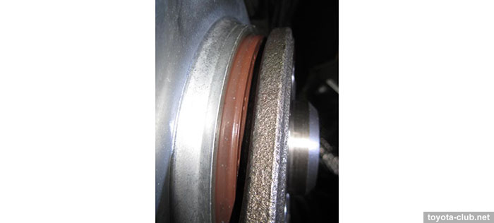
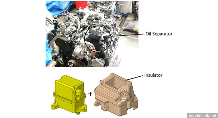
• EG-00435T-TME "1VD-FTV: Oil leakage from rear oil seal due to pressed out" (03.09.2020)
Issue: engine oil level is too low, rear crankshaft oil seal is pressed out.
Production change: insulator (27747-51011) is added at PCV oil separator. Prescription: replace broken parts, install the insulator.
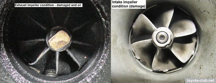
• EG-00433T-TME "1VD-FTV: Loss of power and oil consumption due to turbocharger shaft breakage" (16.02.2021). Issue: power loss, excessive oil consumption, white smoke, abnormal noise - due to turbocharger shaft breakage. Production change: turbine impeller rigidity is improved. Prescription: replace the broken turbocharger with the modified one (17201-51021 ⇒ 17201-51022, 17208-51011 ⇒ 17208-51012).
• Last but not least. Albeit not immediately, but the chip tuners hacked 1VD-FTV control unit and more than actively began to "improve" its characteristics. After that, it became simply pointless to say something about resource and reliability.
• The cost of a high-quality and complete overhaul of this engine (from 5-7 k$ in the norm to 10-12 k$ in a bad case) looks astronomical in absolute terms, although on the other hand, even for cars of the first years of production, this is comparable to only a quarter of their residual value.
Thus, the statistics and real experience of repairmen indicate that 1VD-FTV turned out to be not as problem-free as it is commonly believed. Furthermore, if you ask random people: of which car that initially costing about 100 k$, the engine can crumble before 200.000 km of mileage, probably nine out of ten will name the 'big German three'. Well, at least in that regard, Toyota has taken a step into the world-class premium segment.
|
Toyota engines review
·
AZ ·
MZ ·
NZ ·
SZ ·
ZZ ·
AR ·
GR ·
KR ·
NR ·
ZR ·
AD ·
GD ·
ND ·
VD ·
A25.M20 ·
F33 ·
G16 ·
M15 ·
T24 ·
V35 ·
|
|
|