|
Eugenio,77
1AR-FE, 2AR-FE - basic version. 2AR-FXE - variant for FF hybrid vehicles 2AR-FSE - variant for FR hybrid vehicles, with D-4S system 5AR-FE - chinese analogue of 2AR-FE 6AR-FSE - for FF vehicles, D-4S EMS and VVT-iW 8AR-FTS - turbocharged version with D-4S and VVT-iW, for FF (RX, NX) and FR (IS, GS, Crown) cars
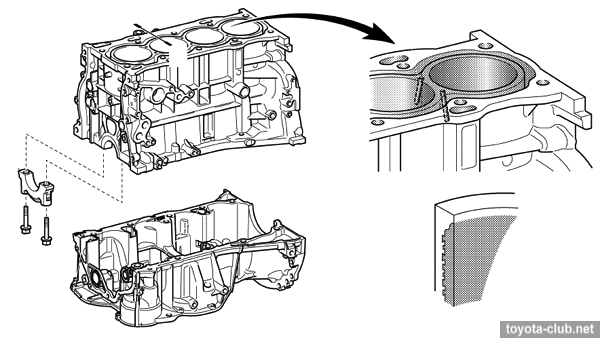
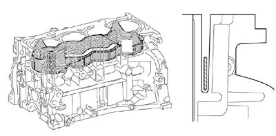
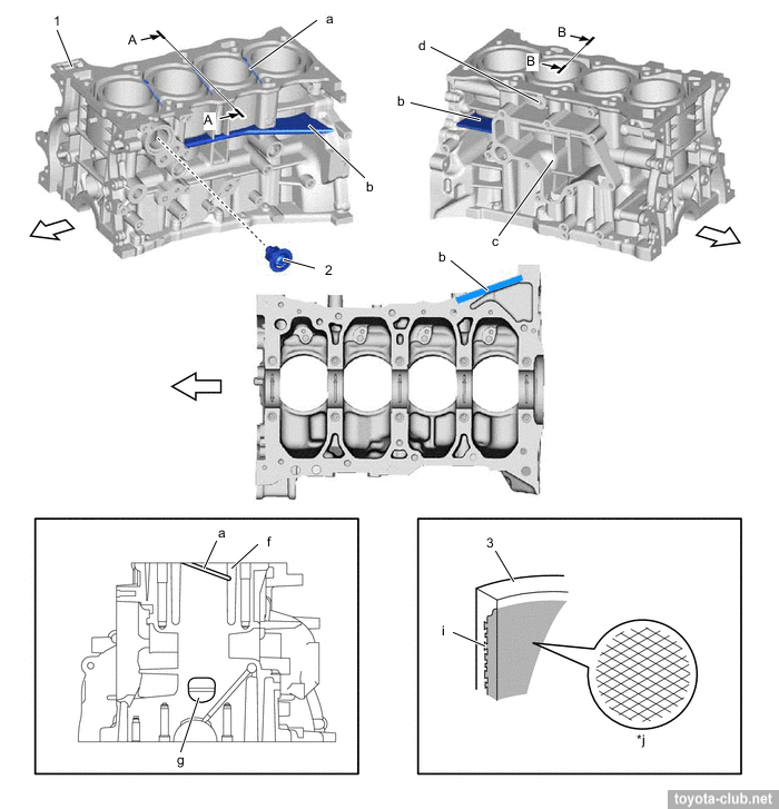
AR series was introduced in 2008 for North American market and for some time remained local endemic. Partly, it replaced 2AZ-FE, partly - filled the emptiness between the 160-hp 2.4 and 280-hp 3.5 for initially FF models. Since early 2010s it installed in E-class cars (Camry family), mid-SUV and vans (RAV4, Highlander, RX, Sienna...). Engine mechanical The cylinder block - aluminum "open deck" with thin cast iron liners. The liners are fused into block and their special rough outer surface promotes strong connection. Of course, no overhaul with reboring provided.
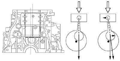
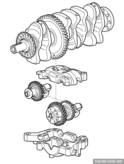
The massive alloy crankcase mounted to block also performs the function of the sump upper part. The axis of the crankshaft has been shifted by 10 mm relative to the cylinder axis lines ("desaxage"), thus reducing the lateral component of the force exerted by the piston to the cylinder wall, reducing wear.
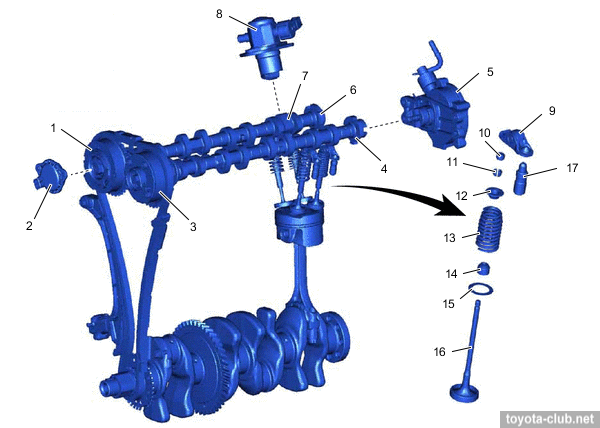
The crankshaft has 8 balance weights, narrowed journals and individual main bearing caps. As usually for Toyota's R4 engines with displacement over 2 liters, the balancer mechanism is installed with direct drive from the crankshaft (by polymer gears to reduce noise).
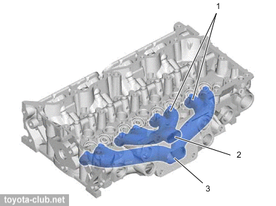
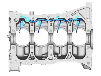
There is the spacer in the water jacket installed, it allows more intensive coolant circulation near the top of the cylinder, which improves heat dissipation and helps to more evenly thermally load.
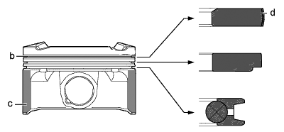
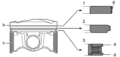
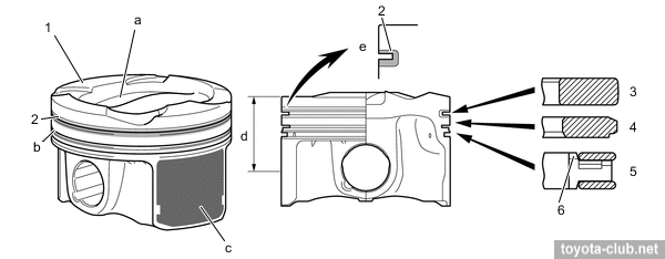
Pistons - alloy, compact T-shaped in projection, with cutted skirt. The groove for the upper compression ring is anodized, the edge of the upper compression ring have anti-wear PVD coating. The pistons are connected to the rods with fully floating pins.
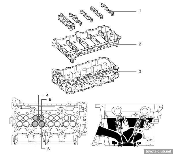
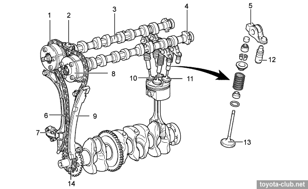
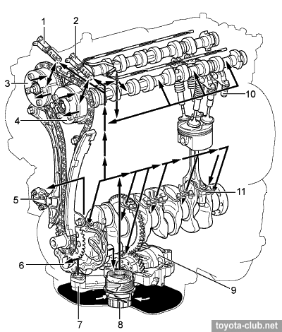
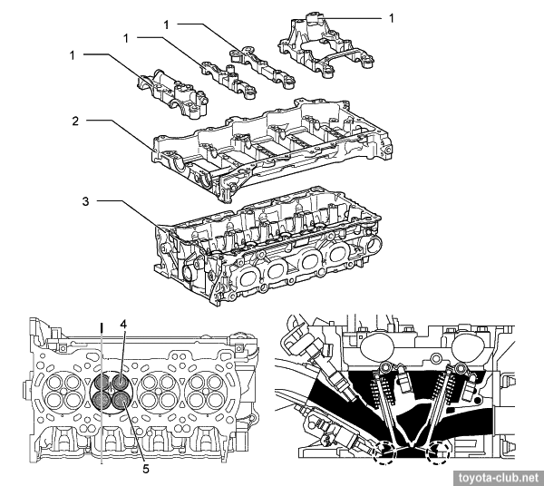
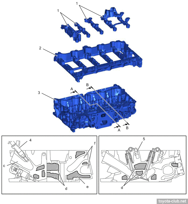
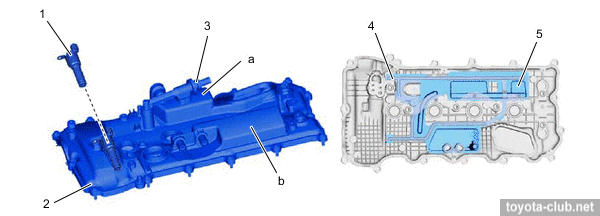
Engines have the same cylinder bore with the piston stroke different. Both are long-stroke, 2.7 has a high average piston speed, but not up to the anti-record of ZR series. The camshafts are installed in a separate housing, which mounted on the cylinder head - it simplifies the design and manufacturing technology of cylinder head. There are valve adjusters and roller rockers in the valve mechanism. The head cover is made of alloy and provided with oil delivery pipe for the rockers lubrication.
Timing drive - 16-valve DOHC, driven by single-row roller chain (pitch 9.525 mm). Hydraulic tensioner (with ratchet mechanism) is installed inside the cover, but is accessible through the service port. The chain is lubricated by separate oil nozzle.
The one of main features of the new engines - VVT actuators both on the inlet and outlet camshafts (DVVT - Dual Variable Valve Timing). Timing variations range - 50° for intake and 40° for exhaust. Lubrication
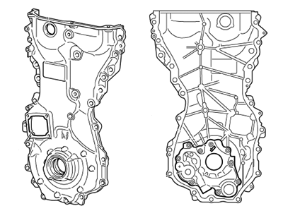
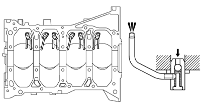
Cycloid oil pump in chain cover is driven directly by the crankshaft. Oil nozzles that lubricate and cool the pistons are provided.
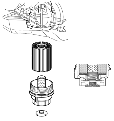
The oil filter is mounted vertically under the engine. Used the collapsible filter with replaceable cartridges.
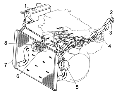
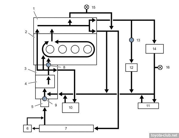
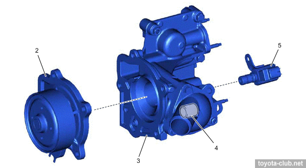
Cooling system Cooling system is classic: pump drive by outer side of serpentine belt, "cold" (80-84°C) mechanical thermostat, heated throttle body, staged radiator fan control. 2AR was equipped with separate fan motor control unit, which allows to adjust fan speed depending on the coolant temperature, refrigerant pressure, vehicle speed and engine speed.
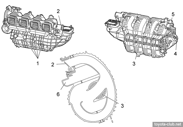
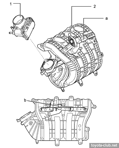
Intake and exhaust Plastic intake manifold mounted at bulkhead side, steel exhaust manifold - at front side. 2AR has AICS vacuum actuator, closing one of the two channels between the air inlet and air filter. At low speeds it should to reduce noise, at high - to increase output. There are ACIS valve with vacuum actuator in the intake manifold, to change the effective length of the intake for output increase. At an average speed and high load ACIS valve is closed and the air flows via long path, in other conditions the valve is opened and air flows via shorter path.
There are Tumble Control System (TCS) valve set with electrical actuator and position sensor at the end of the intake manifold installed. When engine is cold valve is completely closed, to increase flow speed and create turbulence in the combustion chamber, it improves the lean-burn operation immediately after a cold start. Simultaneously, retard ignition timing is set, to reduce the amount of unburned mixture (increase combustion efficiency) and to accelerate heating of the catalyst. The vacuum beyond the valve created contributes to a better fuel atomization and prevents the formation of a liquid film on the air ducts wall. When engine is warmed up, valve is fully open, minimizing the resistance to the air pass.
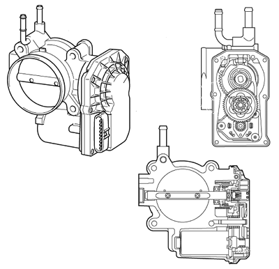
Engine control system (EFI) Fuel injection - multipoint, sequential. - Mass air flow sensor (MAF) - "hot wire" type, combined with the intake temperature sensor. - Throttle valve - fully electronically controlled (ETCS): DC motor, dual-channel non-contact position sensor (Hall effect). ETCS performs some functions of traction control (TRC) and stabilization (VSC).
- Accelerator pedal position sensor - dual-channel non-contact (Hall effect). - Camshaft position sensors - MRE type (magnetoresistive) , provide a digital output signal and work properly at low engine speed. - Knock sensor - wideband "flat" piezoelectric, unlike the old type of resonant knock sensors it feels a wider range of vibration frequencies. - Upstream the catalyst - planar air-fuel ratio sensor (AFS) (89467-), downstream - traditional oxygen sensor. - Injectors with elongate nozzle are installed in the cylinder head and the fuel is injected as close as possible to the intake valves. - Fuel supply - without return line, pulsation damper - external on the fuel rail. Electrical Ignition system - DIS-4 (separate coil for each cylinder). Spark plugs - thin "iridium" SK16HR11 with long threaded portion, hex 14 mm. Charging system - with segment conductor alternators, 100A output. Starting system - new 1.7 kW starter with planetary gear and segment armature coil and permanent magnets instead the field coil. Auxiliary drive - by single serpentine belt with a spring tensioner.
Engine mechanical - High geometric compression ratio - 12.7. - Typical for direct injection engines piston shape with advanced displacers.
- Variable valve timing system VVT-iW - see details. Note. The reviews and articles on the Camry has repeatedly referred to "electrical" valve timing actuator allegedly used on this engine. In fact, visually unliked to previous type, but still hydraulic VVT-iW is installed here. - Implemented a possibility of engine operation by Miller / Atkinson cycle - see details. - High pressure fuel pump is driven by additional cam on the inlet camshaft. - Vacuum pump is driven by rear side of exhaust camshaft. - The high pressure fuel injectors are mounted in cylinder head.
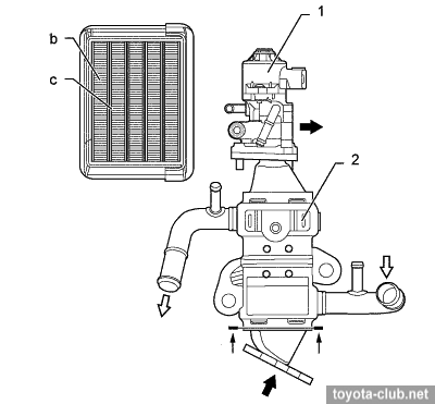
Lubrication - Added oil level sensor in the upper sump. Cooling system - Added water EGR cooler and the cooled EGR control valve. Intake and exhaust - One of the most unpleasant innovation - EGR system, which guarantees the traditional problems with carbon deposits around the inlet duct. EGR control - by step motor.
- Unlike 1AR / 2AR, there are not additional intake geometry actuators, but there was added a manifold for uniform supply of recirculated exhaust gases.
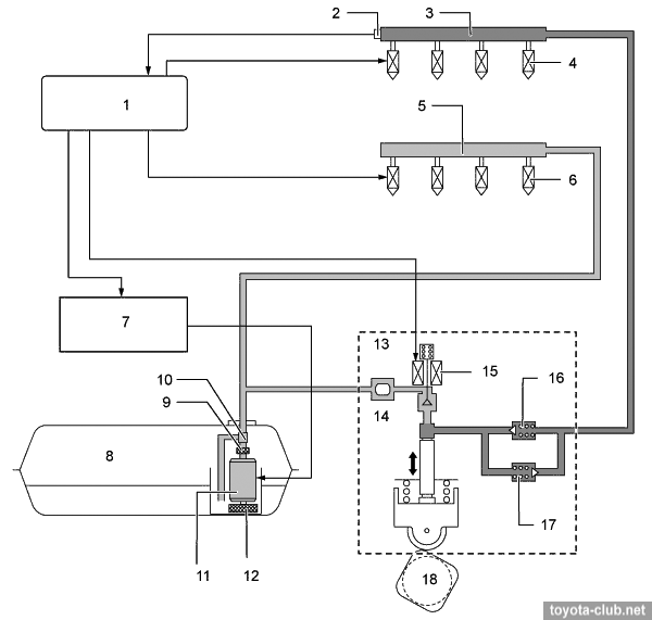
Fuel injection system (D-4S)
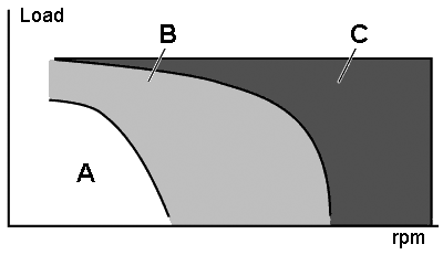
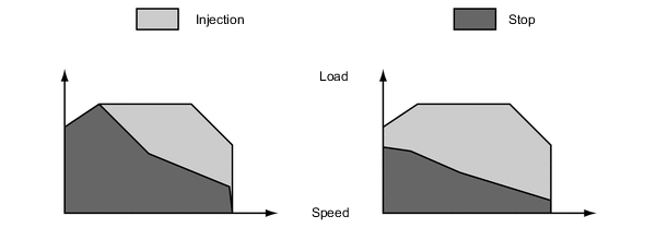
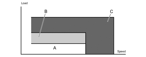
Fuel injection - combined: directly in the combustion chamber and multipoint in the inlet ports. At low to medium loads - combined injection is applied - homogeneous mixture increases the stability of the combustion process and reduces emissions. Under a heavy load use direct fuel injection - the evaporation of the fuel in the cylinder filling mass improves and reduces the tendency to knock.
Operation modes. - Stratified combustion mode. Fuel is supplied in the intake ports on the exhaust stroke. On the intake stroke after the opening of the valves in the cylinder receives a homogeneous lean mixture. At the end of the compression stroke, additional fuel is injected directly into the cylinder, allowing to enrich the mixture near the spark plug. This facilitates the initial ignition, is then distributed on the all lean mixture charge in the remaining volume of the combustion chamber. This mode is applied after a cold start to retard ignition timing and to increase the exhaust gas temperature for accelerate catalyst warming up.
- Homogenous mixture mode. Fuel is supplied in the intake ports on the expansion, exhaust and intake strokes. At the beginning of the intake stroke, additional fuel is injected directly into the cylinder and evenly mixed with the incoming charge. Homogeneous air-fuel mixture is compressed and then ignited. Due to the evaporation of injected fuel, air charge in the cylinder is cooled improves cylinder filling.
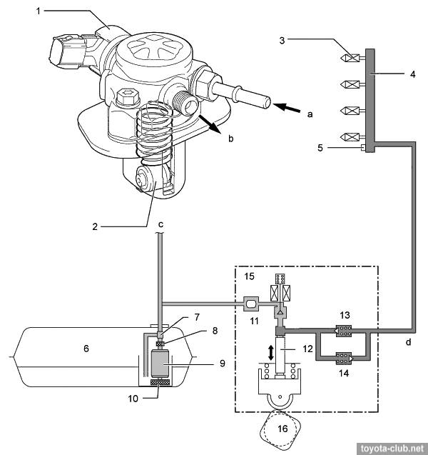
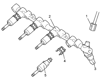
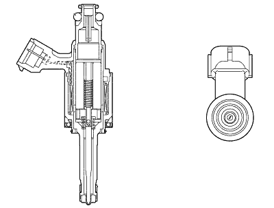
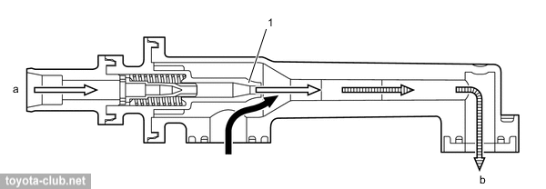
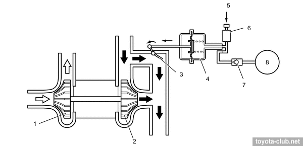
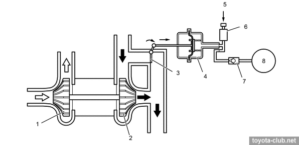
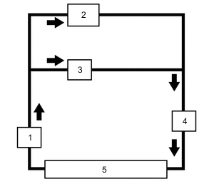
Injection/supply pump. Single-plunger with control valve, relief valve, check valve and pulsation damper at inlet. Mounted on the valve cover and driven by 4-lobes cam of the intake camshaft. The fuel pressure is regulated in the range 4..20 MPa depending on driving conditions.
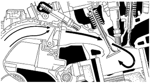
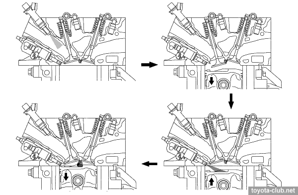
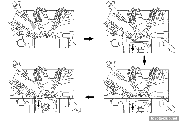
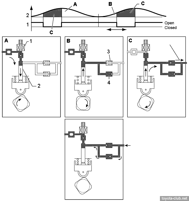
- At inlet stroke (A) the plunger 2 moves downward and fuel draws into the pumping chamber. - At the beginning of the compression stroke (B) part of the fuel is returned while control valve 1 is open (the specified fuel pressure is set). - At the end of the compression stroke control valve is closed and the pressurized fuel through the check valve 3 is supplied into the fuel rail.
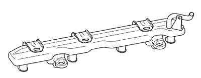
Fuel rail (low pressure). Made of stamped steel, its walls themselves serve as a fuel pulsation damper.
Fuel rail (high pressure). Made of cast iron, contains fuel pressure sensor to provide feedback.
Injectors (high pressure). Slotted nozzle injector injects the fuel into the cylinder as specific shaped spray that draws in a significant amount of air and increases the mass admission. Sealing teflon (PTFE) rings further reduce vibration.
Spark plugs. "Iridium" (Denso FK16HBR-J8), the gap is 0.7-0.8 mm.
As for 6AR, we note the fundamental aspects and differences. Engine mechanical - Variable valve timing system VVT-iW - see details. - Implemented a possibility of engine operation in Miller / Atkinson cycle - see details. - Strengthening, taking into account the increased loads, the cylinder block.
- Supply pump driven by additional cam of the intake camshaft. - Vacuum pump driven by the exhaust camshaft (for brake booster operation and turbocharger control).
- Cylinder head cover made of plastic with integrated oil separator. - Two-stage cooling jacket in the cylinder head. - The exhaust manifold is integrated into the cylinder head.
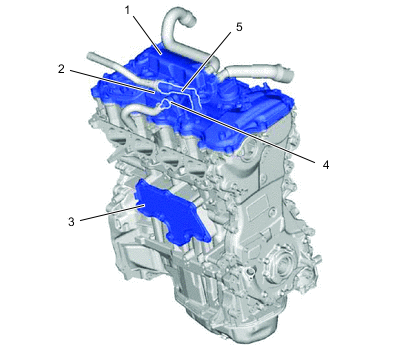
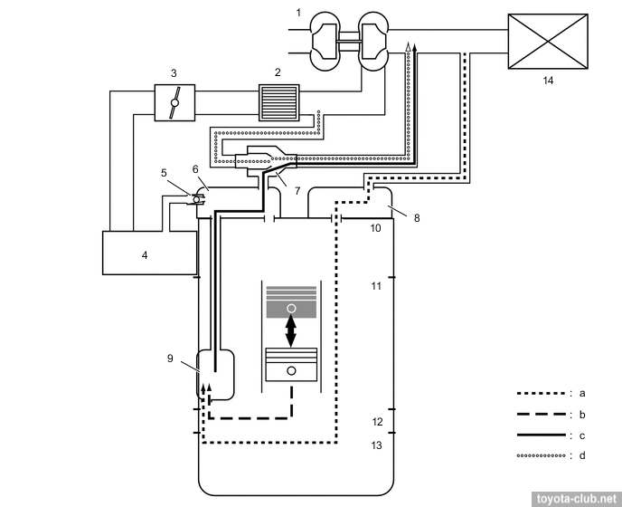
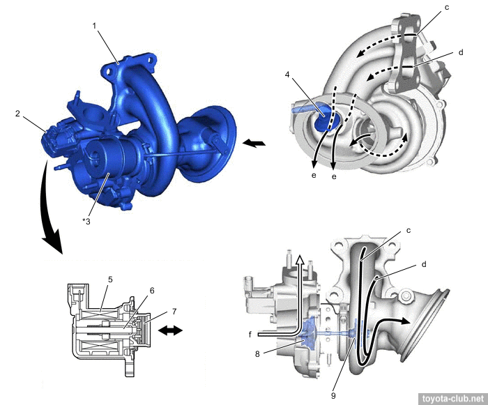
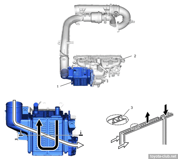
• Crankcase ventilation system. The boost means as increasing the amount of crankcase bypass gases and inability to utilize it by conventional method using the intake vacuum. Therefore, the ejector is mounted in the head cover, so in boost mode gases with high content of hydrocarbons do not fall into the atmosphere but return to the intake and then burn in the cylinder. Obtained with the effective crankcase ventilation Toyota prescribes for 8AR the same engine oil change intervals, as for for atmospheric engines (however this may not be considered a good idea). Also, the additional labyrinth type oil separators and a conventional valve PCV are installed in the cover.
Another separator chamber is installed to crankcase.
In the boost mode crankcase gases discharged via the ejector to intake.
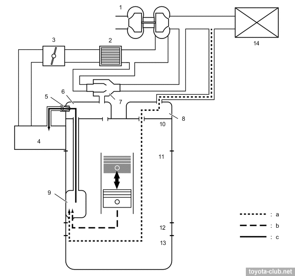
The ejector operates on the principle of Venturi - crankcase gases are sucked into the stream of flowing compressed air.
Without a significant boost, crankcase gases are sucked through a conventional PCV valve.
Cooling system • The engine is equipped by three thermostats: - Traditional thermostat (opening temperature 82°C) in the water inlet controls the coolant flow through the radiator - Thermostat on the cylinder block (opening temperature 82°C) controls the coolant flow through the block, to maximal fast warming up - Manifold thermostat (closure temperature 83°C), in the throttle body coolant line, overlaps the flow at high temperature in order to avoid excessive heating of the intake air.
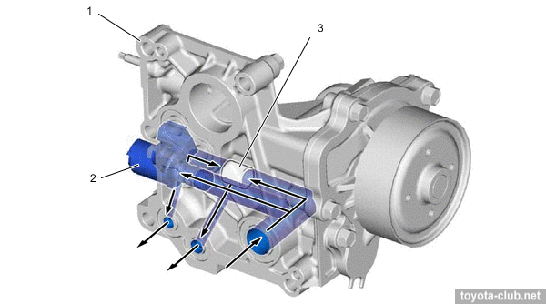
- Built-in cylinder head exhaust manifold allows to cool the exhaust gases before its entering to the turbocharger. Lubrication • The variable discharge oil pump, by analogy with Valvematic ZR engines - see details. • Oil injection control.
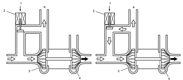
Unlike other engines with common nozzles for piston lubrication and cooling, the ECM can control the oil injection depending on external conditions.
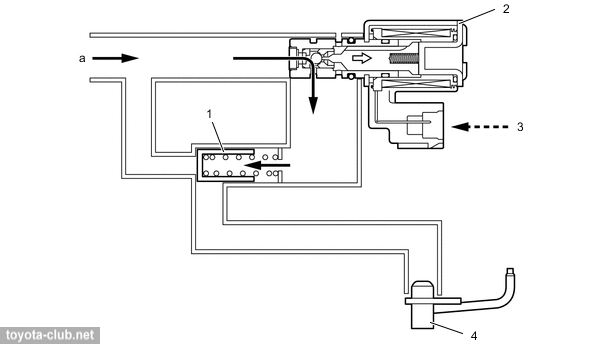
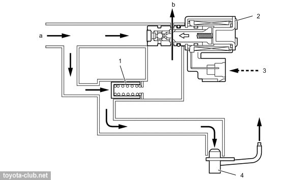
Relief and control valves are installed, oddly enough, in the water inlet.
1) The oil supplied to the rear of the relief valve, cutting off the oil flow to the nozzles.
2) The oil flow to relief valve end stops, the valve opens and the oil is supplied to the nozzles.
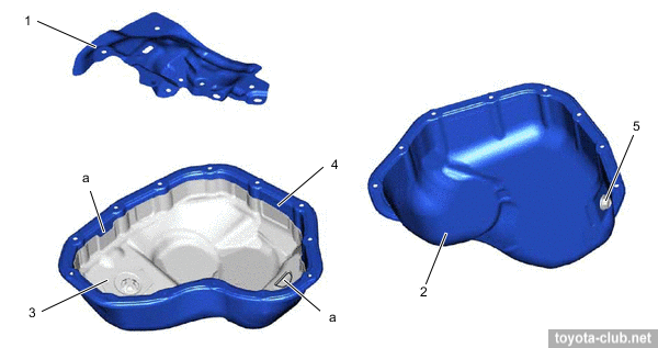
• "Dual-chamber" oil pan, which excludes of the circulation some part of oil. The amount of circulating oil is warmed up more quickly, and a separated volume serves as an additional thermal insulation. After engine stop the oil is mixed through the connecting hole, getting the same quality.
Intake and exhaust • Turbocharger - twin-scroll type - gases from the cylinders 1/4 and 2/3 are supplied to the turbine wheel via separate channels at different angles, which provides a slight increase in efficiency without the using of variable geometry mechanism.
Turbocharger itself is claimed as product of Toyota / Lexus (Miyoshi plant), scroll made of steel with a low content of nickel in order to reduce heat distortion, the impeller is made by electron beam welding. Max boost pressure is about 1.17 bar, the maximum turbine speed is 180,000 rpm. Boost pressure control is performed by classic wastegate valve. - When the engine is stopped - WGT valve open. - When starting control valve shuts off the vacuum supply from the pump to the actuator, which in turn opens WGT. As a result, the hot exhaust gases flow directly into the converter to accelerate its warm-up. - At low loads, when there is no need for a boost, opened WGT reduces resistance and reduces pumping losses at exhaust. By reducing the amount of residual gas the stability of the combustion process is increased.
- At high load WGT is closed and the turbine comes into effective operation.
Air bypass valve serves to prevent a situation where the sudden closing of the throttle rouse to pressure incresing between the turbocharger and the throttle, until the occurrence of reverse flow, accompanied by abnormal noise.
• Independent turbocharger cooling circuit with an electric pump and own radiator is used.
- Intercooler - water-air type. - ECM controls the coolant flow rate and cooling efficiency by electric pump speed.
Fuel injection system (D-4ST) Combined injection system operates in the same conditions as 6AR-FSE, with some distinction in the load/speed range.
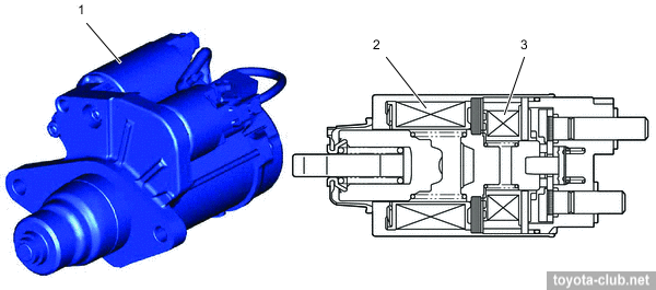
Spark plugs - NGK DILFR7K9G, gap 0.9 mm. Starting system The implementation of Stop-Start caused the installation of new starter TS type (tandem solenoid). Independent solenoids for push out pinion gear and for motor allow engaging with the rotating flywheel, for quick restart immediately after engine shutdown.
Toyota engines review |
|