|
Eugenio,77
GR series introduced first in 2003 for domestic Japanese market. Over time, it replaced previous V6 series MZ and VZ, as well as the legendary R6 series G and JZ. Used for a wide range of models - C/D/E-class cars, vans, mid- and full-size SUV and pickups. Because they are difficult to be attributed as "mass", only its diversity is interesting.
1GR-FE (4.0 EFI VVT) type'04 - longitudinal layout, multipoint injection, mono-VVT. Installed in: 4Runner 210, FJ Cruiser, Fortuner 50, Hilux 20..120, Hilux Surf 210, LC 200, LC 70, LC Prado 120, Tacoma 200, Tundra 30..50. 1GR-FE (4.0 EFI DVVT) type'09 - longitudinal layout, multipoint injection, Dual-VVT. Installed in: 4Runner 280, FJ Cruiser, GX 150, LC 200, LC Prado 150, Tacoma 200, Tundra 50. 2GR-FE (3.5 EFI DVVT) - transverse layout, multipoint injection. Installed in: Alphard 20, Avalon 30..40, Aurion 40, Blade, Camry 40..50, ES 40..60, Estima 50, Harrier 30, Highlander 40, Mark X Zio, Previa 50, RAV4 30, RX 30..L10, Sienna 20..30, Vanguard, Venza, Lotus Evora. 2GR-FKS (3.5 D-4S DVVT-iW) - transverse layout, combined injection, VVT-iW and Miller / Atkinson cycle operation mode. Installed in: RX L20. 2GR-FKS (3.5 D-4S DVVT-iW) - longitudinal layout, combined injection, VVT-iW and Miller / Atkinson cycle operation mode. Installed in: GS L10, Tacoma 300. 2GR-FSE (3.5 D-4S DVVT) - longitudinal layout, combined injection. Installed in: Crown 180..200..210, GS 190..L10, IS 20..30, Mark X 120..130, RC. 2GR-FXE (3.5 EFI DVVT) - transverse layout, multipoint injection, for hybrid vehicles. Installed in: RX L10, Highlander 40. 2GR-FXE (3.5 D-4S DVVT) - longitudinal layout, combined injection, for hybrid vehicles. Installed in: Crown 210, GS L10. 2GR-FXS (3.5 D-4S DVVT-iW) - transverse layout, combined injection, VVT-iW and Miller / Atkinson cycle operation mode, for hybrid vehicles. Installed in: RX L20. 2GR-FZE (3.5 EFI DVVT) - transverse layout, multipoint injection, supercharged. Installed in: TRD Aurion, Lotus Evora, Exige. 3GR-FE (3.0 EFI DVVT) - longitudinal layout, multipoint injection. Installed in: Crown 180..200 CHN, GS 190, IS 20, Reiz 120..130. 3GR-FSE (3.0 D-4 DVVT) - longitudinal layout, direct injection. Installed in: Crown 180..200, GS 190, Mark X 120. 4GR-FSE (2.5 D-4 DVVT) - longitudinal layout, direct injection. For Toyota brand models at Japanese market since the early 2010s used deforced variant. Installed in: Crown 180..200..210, GS L10, IS 20..30, Mark X 120..130. 5GR-FE (2.5 EFI DVVT) - longitudinal layout, multipoint injection, for Chinese market. It is not a version of 4GR, but separate motor on the basis of 3GR-FE. Installed in: Crown 180..200 CHN, Reiz 120..130. 6GR-FE (4.0 EFI DVVT) - longitudinal layout, multipoint injection, for Chinese market commercial vehicles. Analogue of 1GR-FE type'09. Installed in: Coaster 50 CHN. 7GR-FKS (3.5 D-4S DVVT-iW) - longitudinal layout, combined injection, VVT-iW and Miller / Atkinson cycle operation mode, for Chinese market. Analogue of 2GR-FKS. Installed in: LC Prado 150 CHN. 8GR-FKS (3.5 D-4S DVVT-iW) - longitudinal layout, combined injection, VVT-iW and Miller / Atkinson cycle operation mode. Analogue of 2GR-FKS. Installed in: LC Lexus LS. 8GR-FXS (3.5 D-4S DVVT-iW) - longitudinal layout, combined injection, VVT-iW and Miller / Atkinson cycle operation mode. Analogue of 2GR-FKS. Installed in: Lexus LC, Lexus LS, Crown 220.
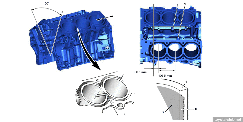
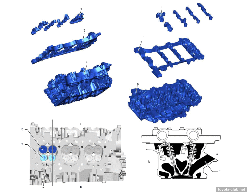
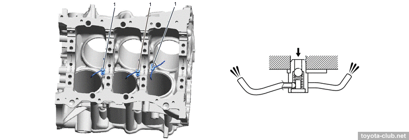
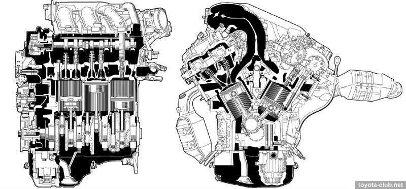
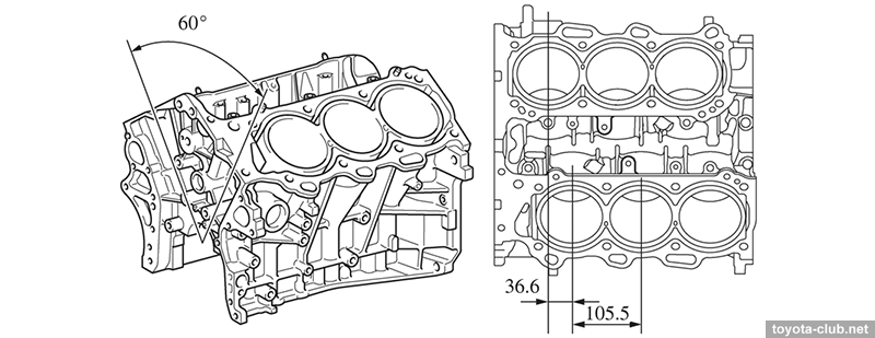
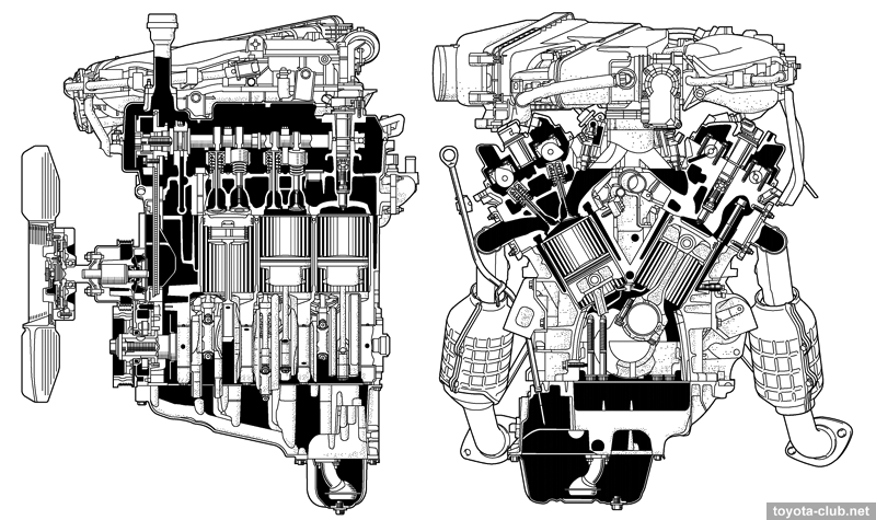
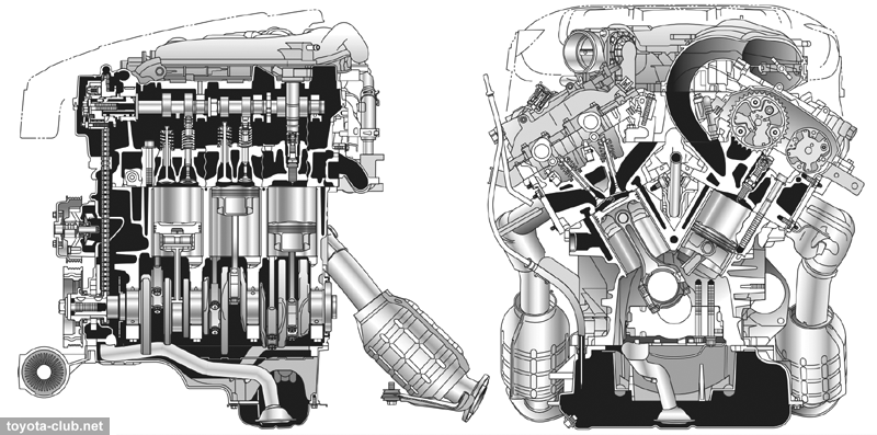
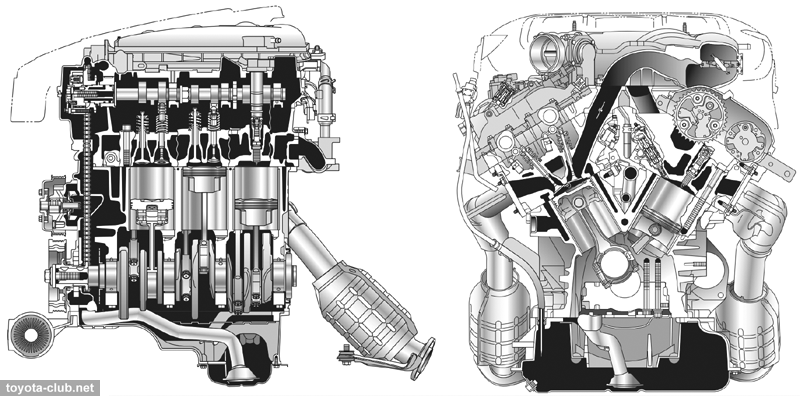
If at the beginning of the 2010s the 2GR-FE was the most massive engine in the series, then by the end of the decade it was replaced by the 2GR-FKS, which also deserves a detailed description of the design. Cylinder block The cylinder block - aluminum "open deck" with thin cast iron liners, cylinder bank angle is 60°. The liners are fused into block and their special rough outer surface promotes strong connection. There are sloping coolant channels drilled between the cylinders.
There are the spacers in the water jacket installed, it allows more intensive coolant circulation near the top of the cylinder, which improves heat dissipation and helps to more evenly thermally load.
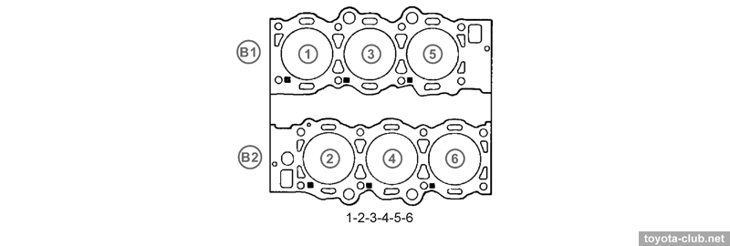
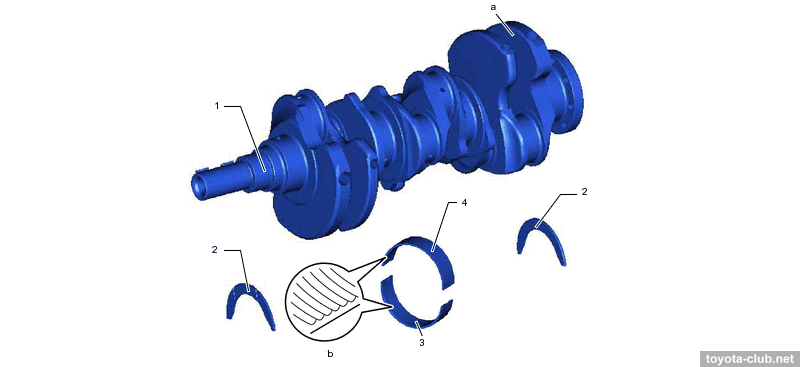
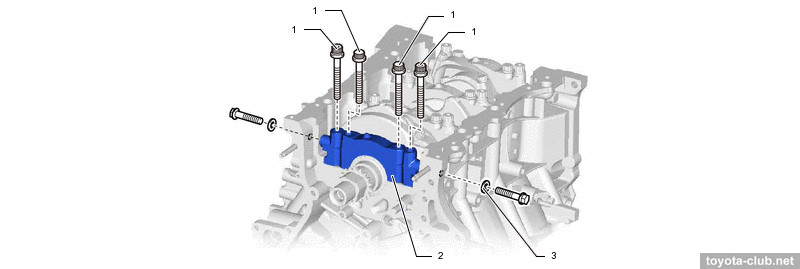
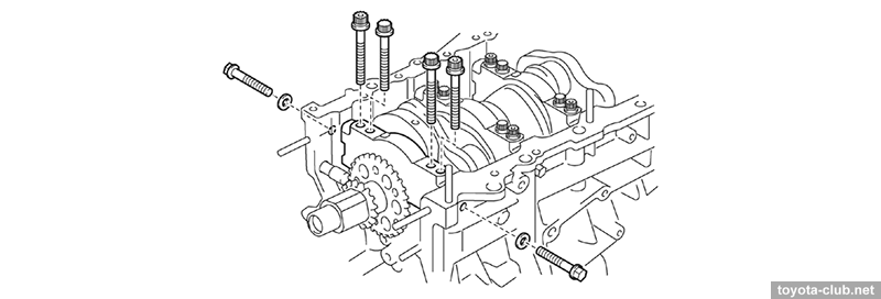
Forged steel crankshaft with 4 journals and 5 balance weights is held by individual main bearing caps, which are fastened by four main bolts and by another two side bolts to block walls for maximum rigidity.
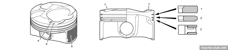
Pistons - of aluminum alloy, compact T-shaped in projection, with cutted skirt, all the same size and the same for each bank. The working part of the skirt is polymer coated. The pistons are connected to the rods with fully floating pins.
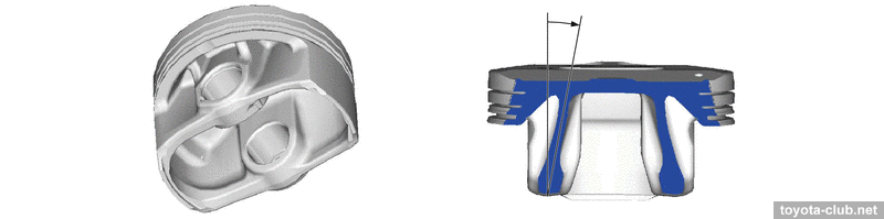
The "walls" of the piston are noticeable sloped, which should better distribute the load to the piston pin at the expansion stroke.
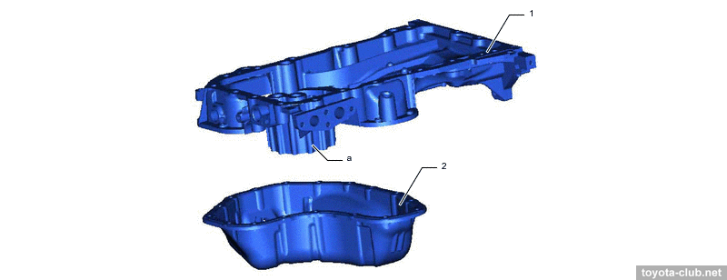
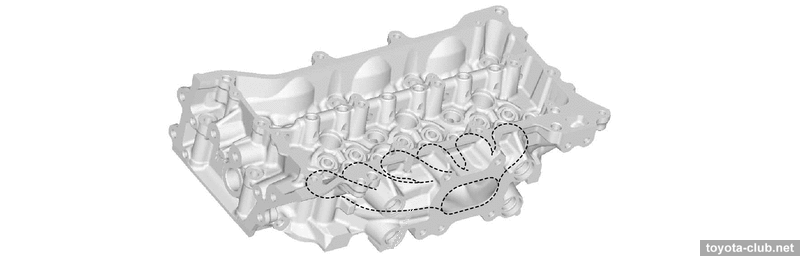
The oil sump consist of massive upper part (additionally connected to transmission for stiffness) and stamped steel lower sump.
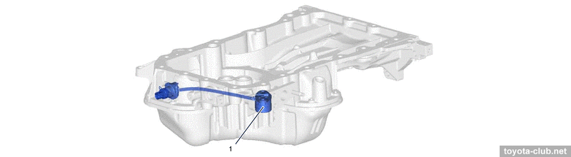
The oil level sensor is installed in the crankcase (functionally, a low-level sensor switch).
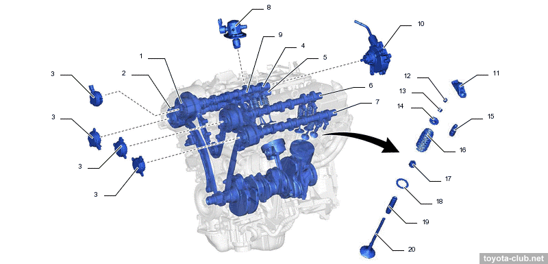
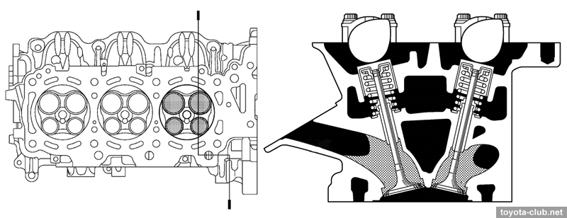
Cylinder head The camshafts are installed in a separate housings, which mounted on the cylinder heads - it simplifies the design and manufacturing technology of cylinder head, however, another joint of parts has appeared that requiring sealing.
The exhaust manifolds are integrated into the cylinder heads.
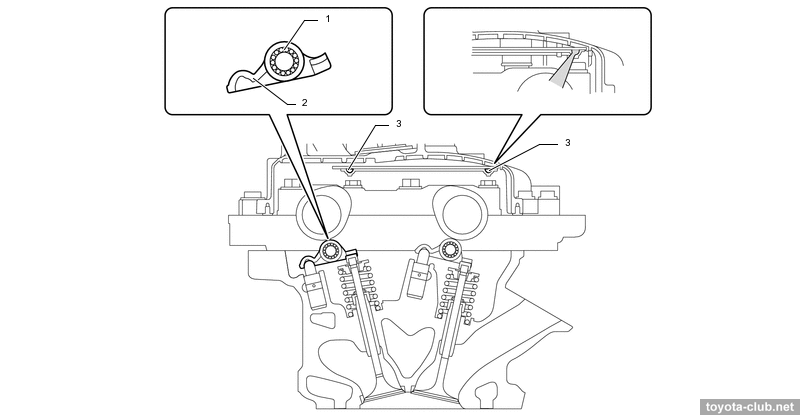
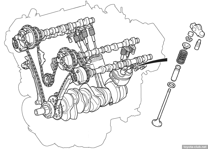
There are valve adjusters and roller rockers in the valve mechanism.
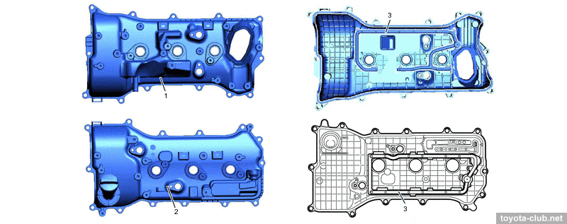
The head covers are made of polymer and provided with oil delivery pipe for the rockers lubrication, and oil baffle plates.
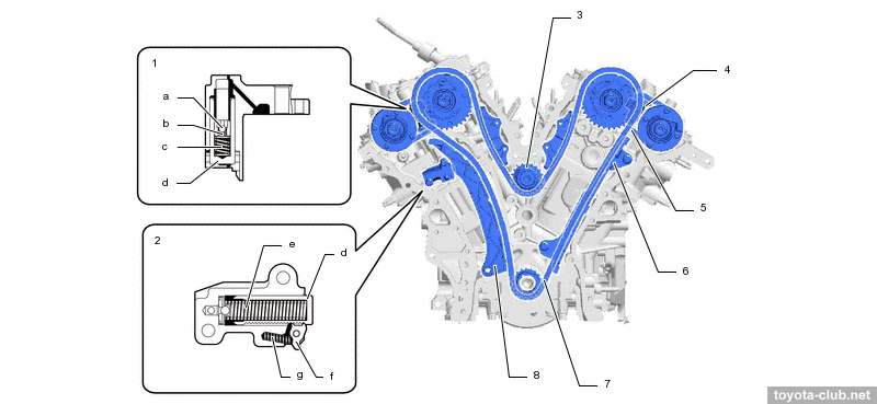
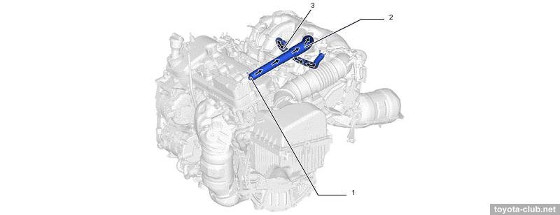
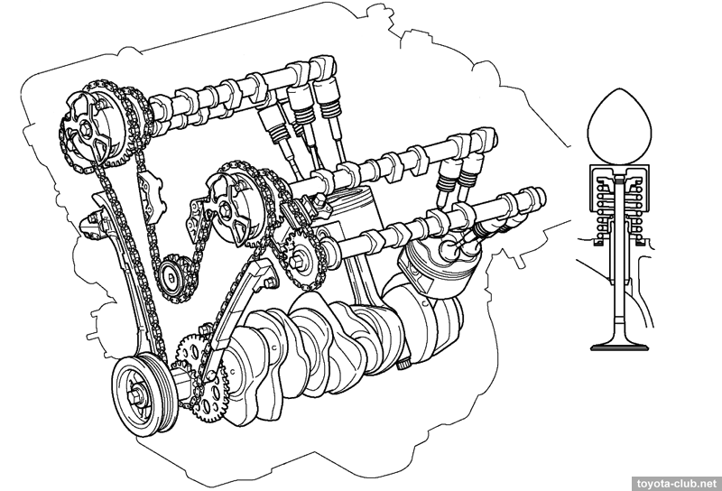
Timing drive Timing drive is "two-step". From the crankshaft by the primary roller chain (pitch 9.525 mm) intake camshafts are driven, and two short secondary chains for exhaust camshafts drive are used. Primary circuit tensioner - with a ratchet mechanism, spring and return valve, secondary chain tensioner have not ratchet, but also is spring enforced.
VVT-iW system (Variable Valve Timing - intelligent Wide) allows to smoothly change the valve timing according to engine operating conditions: VVT actuators both for the intake and exhaust camshafts are installed, timing variations range is 75° for intake and 41.5° for exhaust. More about Toyota VVT operation. Implemented a possibility of engine operation by Miller / Atkinson cycle.
The intake camshaft drives the vacuum pump.
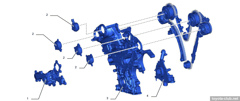
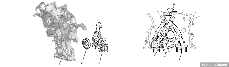
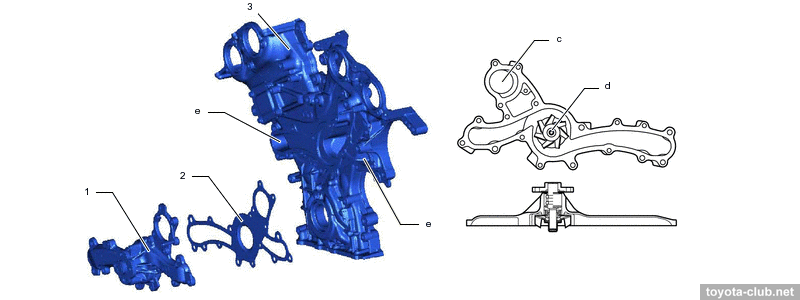
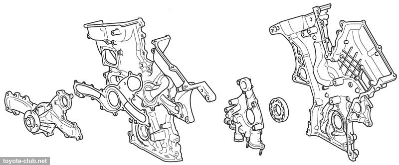
The coolant pump and oil pump are installed in the timing chain cover, respectively, oil and coolant passages in the cover are provided.
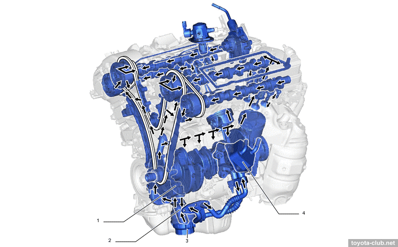
Lubrication
Cycloid oil pump in chain cover is driven directly by the crankshaft, the excess oil is not drain to sump but feed back to the pump inlet.
Oil nozzles that lubricate and cool the pistons are provided.
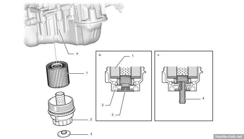
The collapsible filter with replaceable cartridge and plastic cover is installed, filter housing is built into the upper sump.
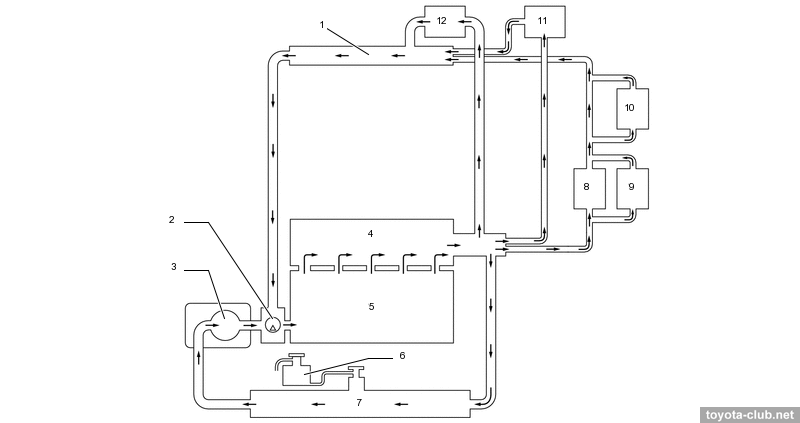
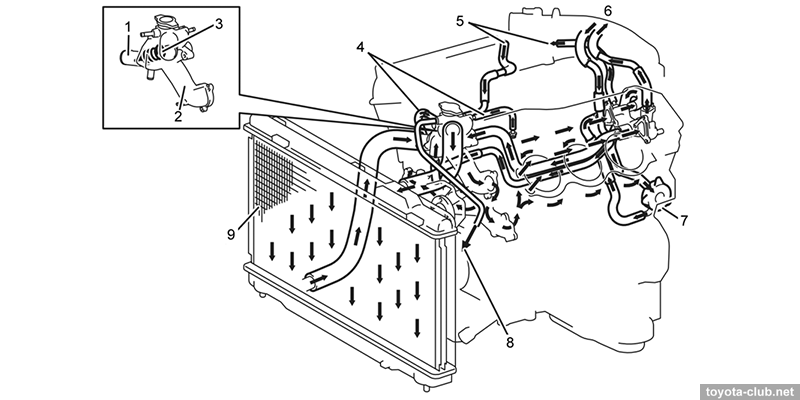
Cooling
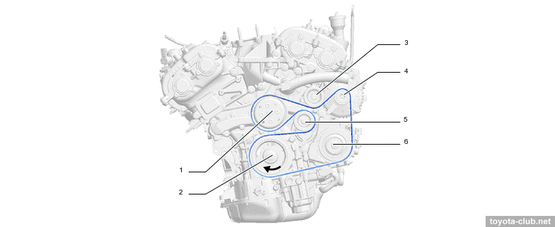
The pump is driven by common serpentine belt.
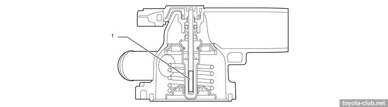
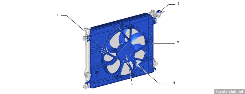
Thermostat with electric heater, nominal opening temperature 85-89°C - engine is about 5 degrees "hotter" than the 2GR-FE. The current supply to the thermostat heater allows to increase its opening under significant load conditions, lowering the temperature in advance and providing higher power output without the risk of detonation.
The fan motor control unit allows to adjust fan speed steplessly depending on the coolant temperature, climate control, vehicle speed and engine speed. The fan - single, large diameter.
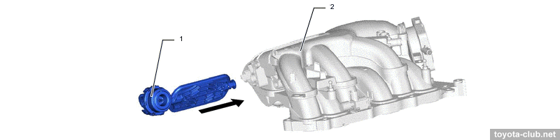
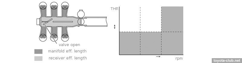
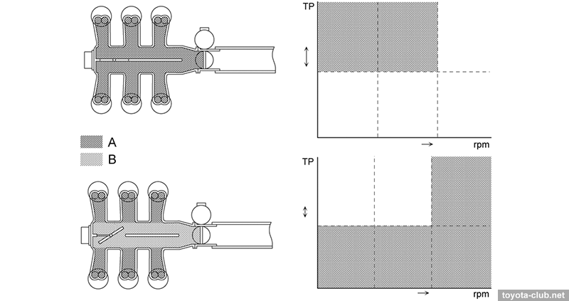
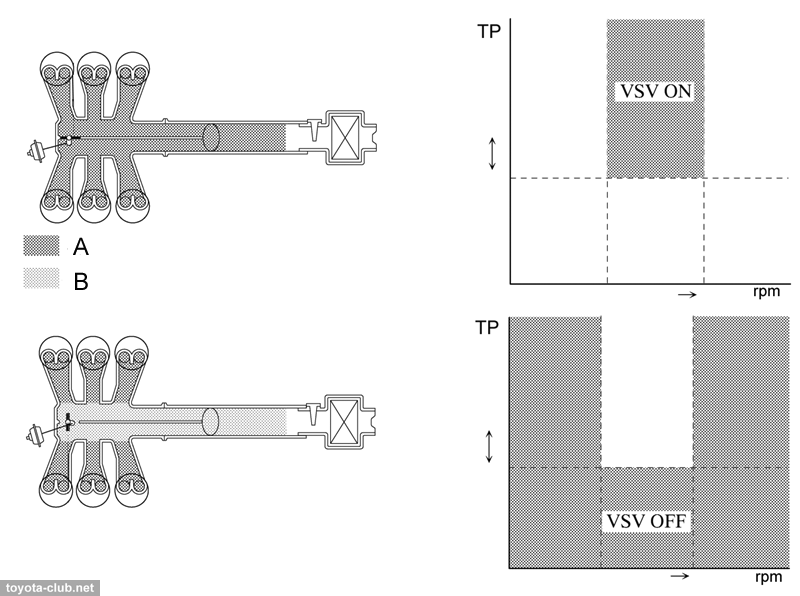
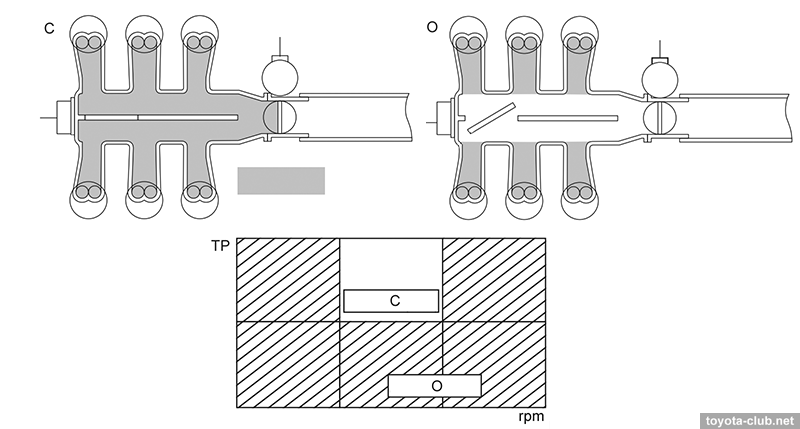
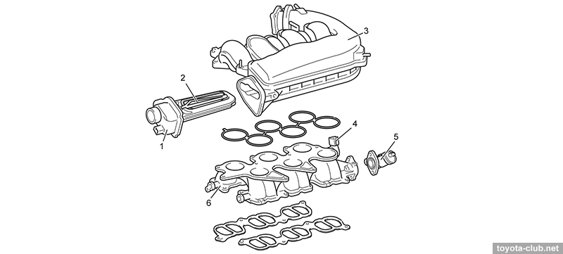
Intake and exhaust ACIS valve installed in the intake receiver, allows to change the effective length of the intake duct for better performance.
At low and medium speed and high load ACIS valve is closed and the air flows via long path.
In other conditions the valve is opened and air flows via shorter path.
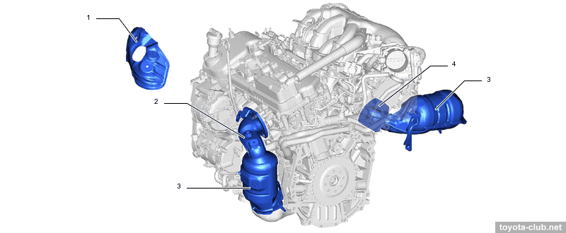
Exhaust collectors have been simplified as much as possible.
There is the mechanical valve in the muffler that regulates the flow of exhaust gases. At low speed closed valve helps to reduce noise, at high speeds it is opened reducing the back-pressure.
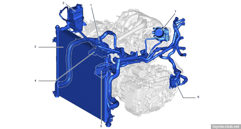
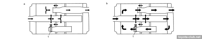
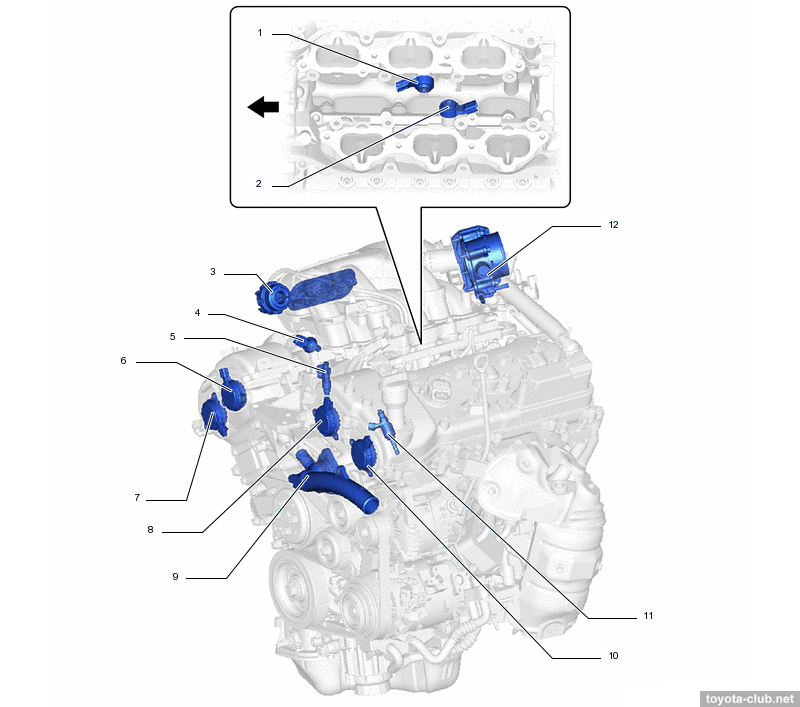
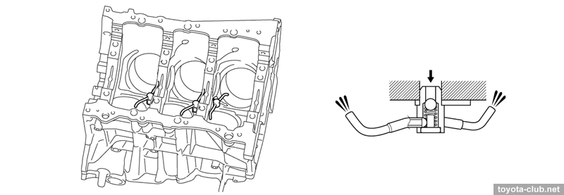
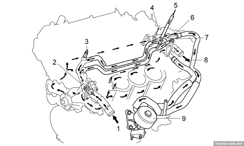
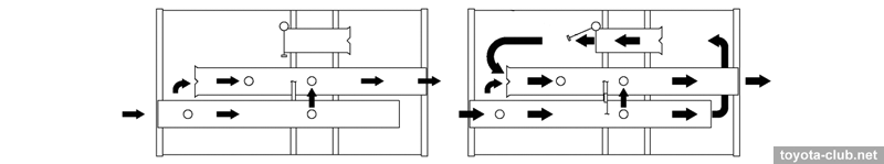
• PCV (crankcase ventilation system). At low load, blow-by gas is suctioned through the PCV valve into the intake manifold and burned in the cylinders, fresh air enters the crankcase through the head cover to maintain the required pressure. At high load, blow-by gas is forced through the PCV valve and the ventilation hose 2 into the intake manifold.
Blow-by gas pass through the cylinder block and the left cylinder head for best oil separation.
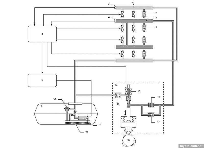
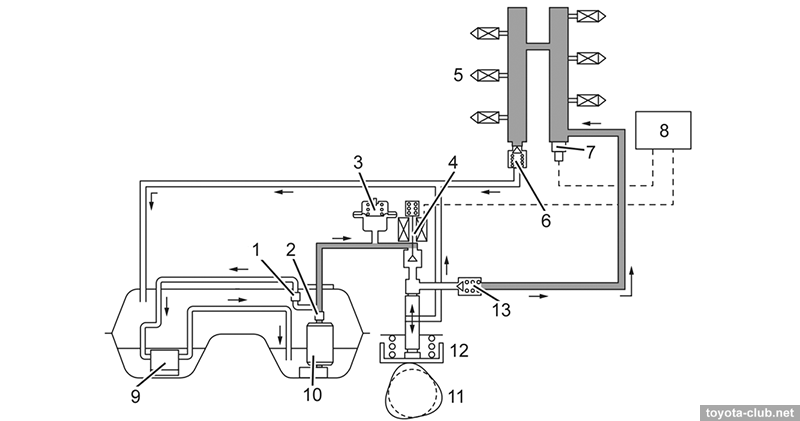
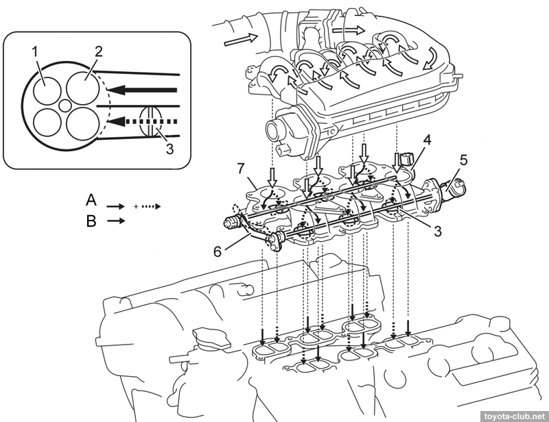
Fuel injection system (D-4S) Fuel injection - combined: directly in the cylinder and multipoint in the inlet ports.
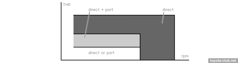
At low to medium loads and low speeds - combined injection is applied - homogeneous mixture increases the stability of the combustion process and reduces emissions. Under a heavy load use direct fuel injection - the evaporation of the fuel in the cylinder filling mass improves and reduces the tendency to knock.
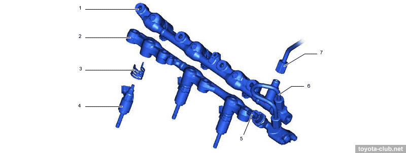
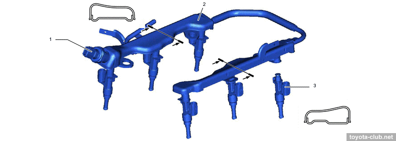
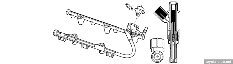
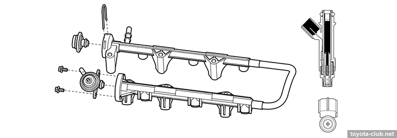
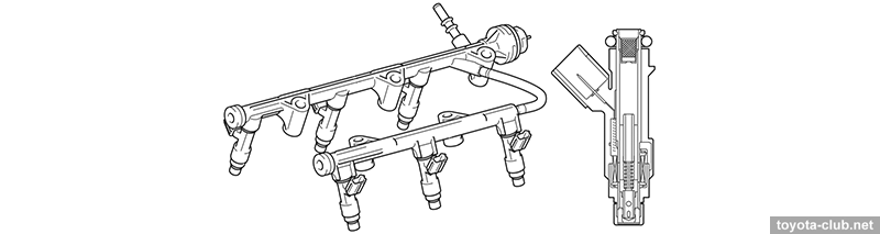
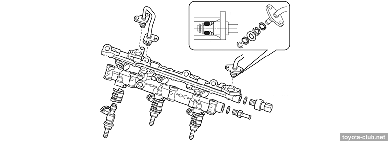
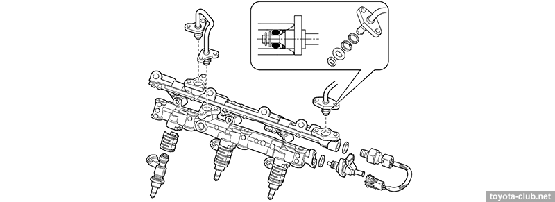
- Stratified combustion mode. Fuel is supplied in the intake ports on the exhaust stroke. On the intake stroke after the valves are opened a homogeneous mixture flows in the cylinder. At the end of the compression stroke, additional fuel is injected directly into the cylinder, allowing to enrich the mixture near the spark plug. This facilitates the initial ignition, is then distributed on the all lean mixture charge in the remaining volume of the combustion chamber. This mode is applied after a cold start to retard ignition timing and to increase the exhaust gas temperature for accelerate catalyst warming up. - Homogenous mixture mode. Fuel is supplied in the intake ports on the expansion, exhaust and intake strokes. At the beginning of the intake stroke, additional fuel is injected directly into the cylinder. A homogeneous mixture is made in the cylinder by either joint or independent operation of two types of injection. Due to the evaporation of injected fuel, air charge in the cylinder is cooled improves cylinder filling. Fuel rail (high pressure) - made of pressed steel fuel, contains fuel pressure sensor to provide feedback. Injectors are held by spring holders that reduce vibration and prevent them from moving during starting (when the pressure in the cylinder is higher than the fuel pressure in the rail).
Fuel rail (low pressure) - steel-stamped; its walls themselves serve as a damper for fuel pressure pulsations. The pressure sensor installed in the rail.
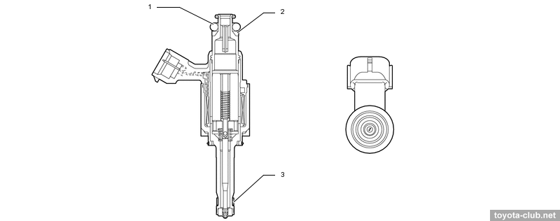
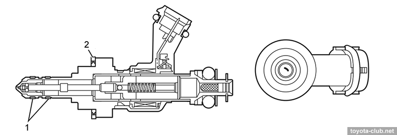
Injectors (high pressure) - with a slot nozzle, inject fuel into the cylinders as a torch for maximum atomization of gasoline. PTFE seal rings further reduce nozzle noise and vibration.
Injectors (low pressure) - with a long 12-point nozzle.
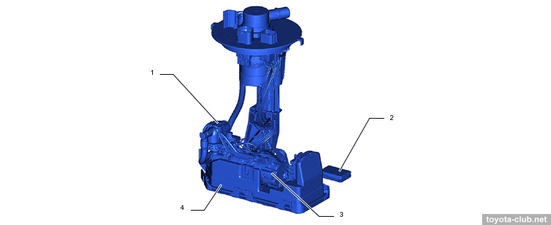
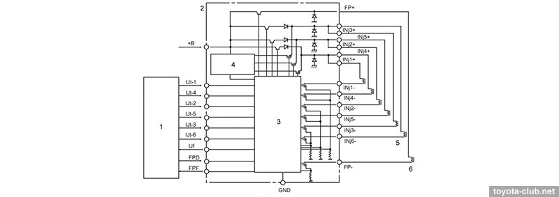
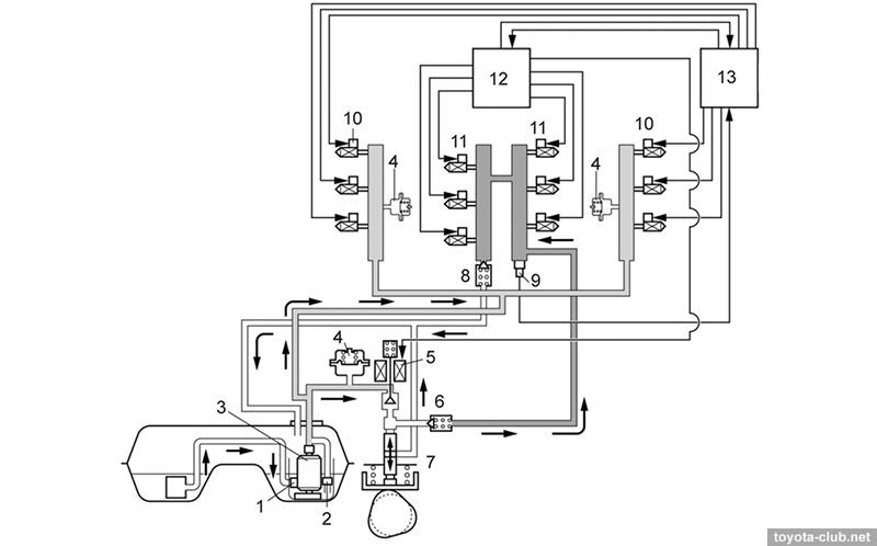
Fuel pump (low pressure) - delivers fuel from the tank to the injection pump and to the low pressure injectors. The pump is controlled by the ECM through a separate control unit.
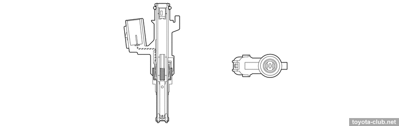
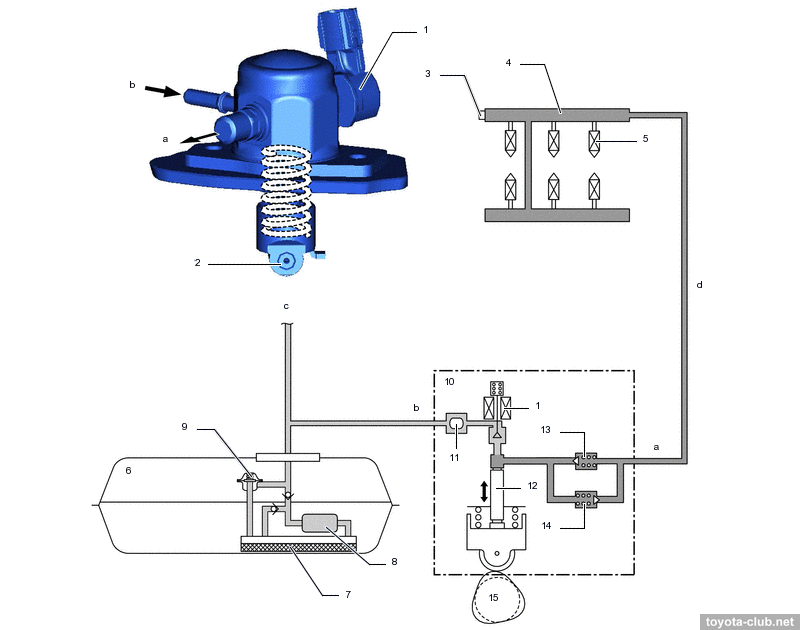
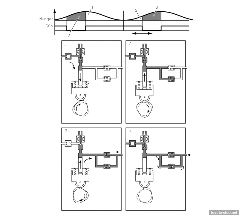
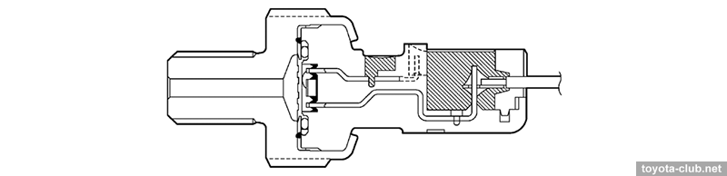
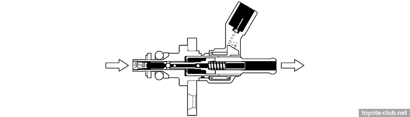
Fuel pump (high pressure) - single-plunger with control valve, relief valve, check valve and pulsation damper at inlet. It is mounted on the valve cover and is driven by a cam of the exhaust camshaft .
- At inlet stroke the plunger moves downward and fuel draws into the pumping chamber. - At the beginning of the compression stroke part of the fuel is returned while control valve is open (the specified fuel pressure is set). - At the end of the compression stroke control valve is closed and the pressurized fuel through the check valve is supplied into the fuel rail. - If the pressure in the manifold becomes abnormally high, a mechanical relief valve opens to dump part of the fuel back to the pump.
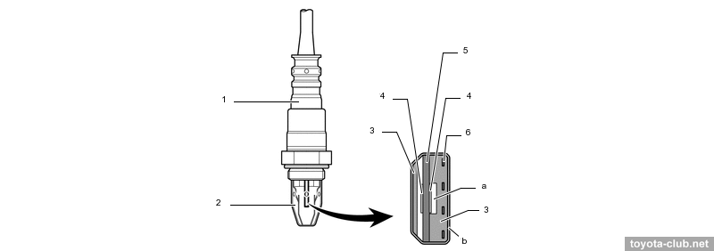
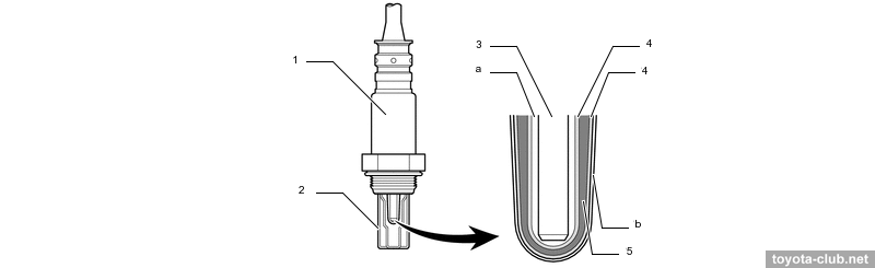
The fuel pressure is regulated depending on the driving conditions: at idle speed the minimum 2.4 MPa is maintained, at low speed - within 2.4..14 MPa, at medium speed - within 2.4..20 MPa, at high speed - within 2.4..18 MPa. · ECM - with 32-bit processor. · Oxygen sensors - air-fuel ratio sensor (AFS) - planar type.
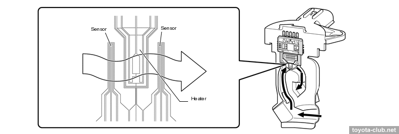
· Mass air flow sensor (MAF) - "slot-in" type - air flow is determined by the temperature difference of two sensing elements, between which the heater is located.
· Fuel pressure sensors for high and low pressure circuits. · Crankshaft and camshaft position sensors - MRE type (magnetoresistive), provide a digital output signal and work properly at low engine speed.. · Throttle valve - electronically controlled (ETCS): DC motor, dual-channel non-contact position sensor (Hall effect). · Accelerator pedal position sensor - dual-channel non-contact (Hall effect). · Knock sensors - "flat" wideband piezoelectric, installed on each bank at the middle cylinder zone.
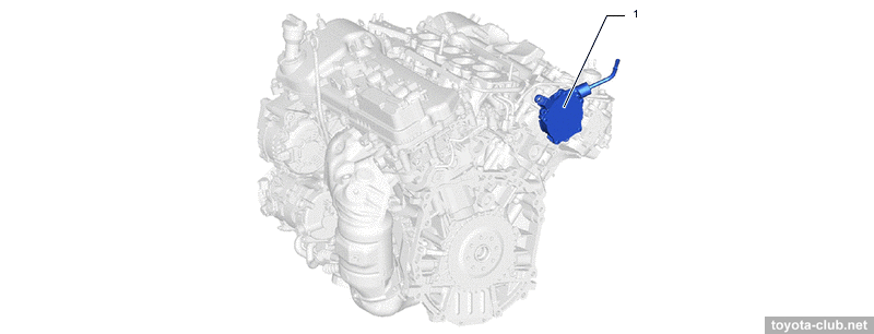
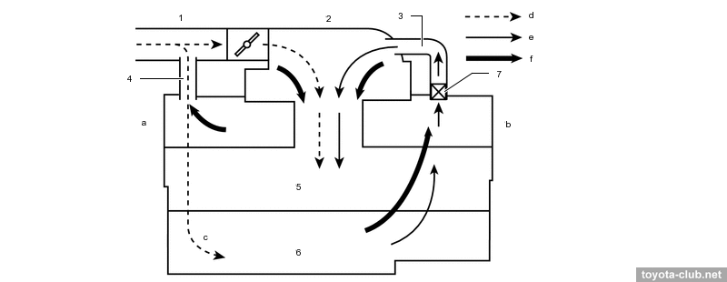
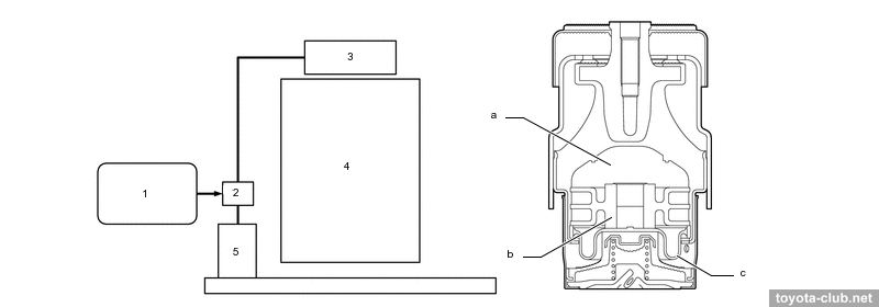
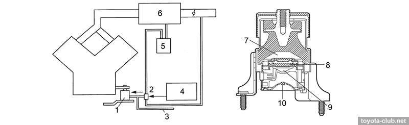
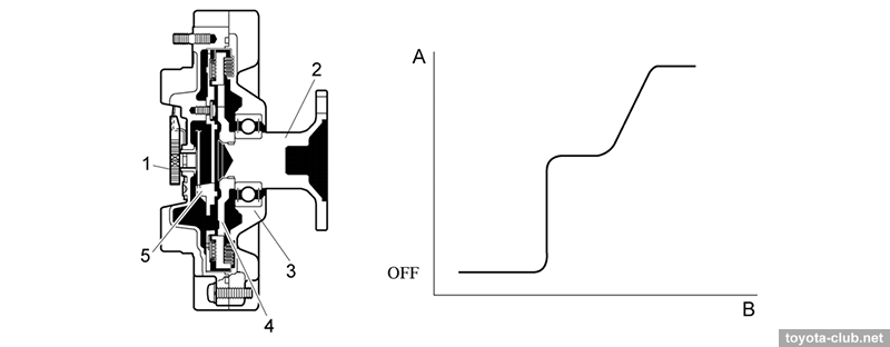
• Active front mount used to reduce idle vibration. If the valve is off, the vacuum does not flow to the mount and the diaphragm is closed - the liquid flows outside the orifice, increasing the damping force. If the valve is on, vacuum is applied to the mount and the diaphragm is open - fluid flows inside the orifice, improving comfort at idle or lock-up.
• EVAP system (fuel evaporation) for Euro-version is the most simple, without any feedback.
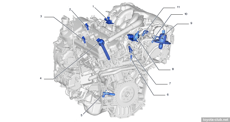
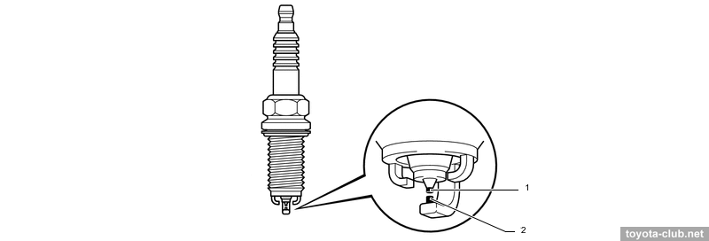
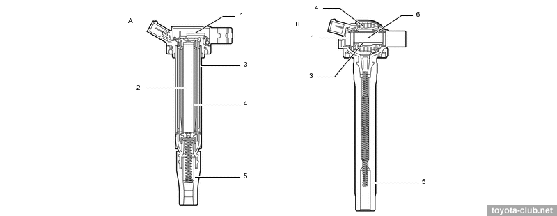
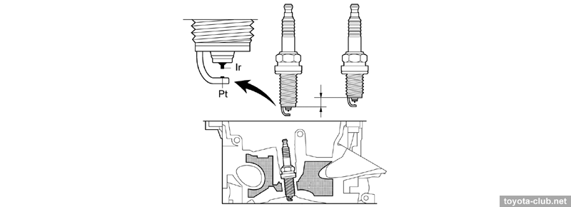
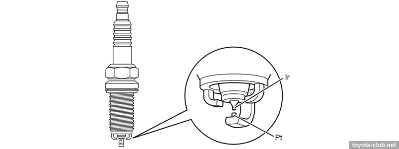
Electrical Ignition system - DIS-6 (separate coil for each cylinder). Spark plugs - "iridium" (Denso FK20HBR8 - central electrode of iridium alloy, ground electrode with platinum tip, two additional side electrodes), with a long threaded portion (thereby cooling channel can be expanded in the head to improve heat dissipation).
Starter - new 1.7 kW type with planetary gear and segment armature coil. Auxiliary drive - by serpentine belt with automatic spring tensioner.
Cylinder block The cylinder block - aluminium "open deck" with thin cast iron liners, cylinder bank angle is 60°. The liners are fused into block and their special rough outer surface promotes strong connection. There are additional channels for coolant between the cylinders, and there are not spacer in the water jacket of 2GR-FE. Of course, no overhaul with reboring provided.
The oil sump consist of massive upper part (additionally connected to transmission for stiffness) and stamped steel lower sump. Forged steel crankshaft with 4 journals and 5 balance weights is held by individual main bearing caps, which are fastened by four main bolts and by another two side bolts to block walls for maximum rigidity.
Pistons - of aluminium alloy, compact T-shaped in projection, with cutted skirt, all the same size and the same for each bank (as opposed to MZ series). The groove for the upper compression ring has alumite coating and friction reducing polymer coating is applied on the skirt. Thin rings have protective coatings: upper compression - by PVD, lower - anti-corrosion, oil scraper - by gas nitriding. The pistons are connected to the rods with fully floating pins.
Cylinder head The camshafts are installed in a separate housing, which mounted on the cylinder head - it simplifies the design and manufacturing technology of cylinder head. The intake ports are paired, to improve the air flow characteristics the diameter decreases towards the combustion chamber. There are valve adjusters and roller rockers in the valve mechanism. The head covers are made of alloy and provided with oil delivery pipe for the rockers lubrication. Timing drive Timing drive is "two-step". From the crankshaft by the primary roller chain (pitch 9.525 mm) intake camshafts are driven, and two short secondary chains for exhaust camshafts drive are used. Primary circuit tensioner - with a ratchet mechanism, spring and return valve, secondary chain tensioner have not ratchet, but also is spring enforced. The chains are lubricated by separate oil nozzles.
Camshaft cams - with a concave profile (thus increasing valve lift at the beginning and at the end of the opening phase, which improves the cylinder admission). VVT actuators both on the inlet and outlet camshafts are installed (DVVT - Dual Variable Valve Timing). Timing variations range - 40° for intake and 35° for exhaust. The auxiliary spring is installed in VVT actuator of exhaust camshaft to apply a torque to the rotor in the advance direction for secure locking it with pin after engine stall. The water pump and oil pump are installed in cast timing chain cover, respectively, oil and coolant passages in the cover are provided.
Lubrication system Cycloid oil pump in chain cover is driven directly by the crankshaft, the excess oil is not drain to sump but feed back to the pump inlet. Oil nozzles that lubricate and cool the pistons are provided.
The collapsible filter with replaceable cartridges are used, filter housing is built into the upper sump.
Cooling system Cooling system is classic: pump drive by outer side of serpentine belt, pump impeller of stainless steel, mechanical thermostat (80-84°C). The throttle body is heated to counteract freezing. Some versions are equipped with oil cooler.
The engine was equipped with separate fan motor control unit, which allows to adjust fan speed depending on the coolant temperature, refrigerant pressure, vehicle speed and engine speed. Intake and exhaust There are ACIS valve with electrical drive in the upper intake manifold installed, to change the effective length of the intake for output increase. At low and medium speed and high load ACIS valve is closed and the air flows via long path, in other conditions the valve is opened and air flows via shorter path.
AICS vacuum actuator closes one of the two channels between the air inlet and air filter. At low and middle speed the valve closes one of the channels, so the air passes to filter via smaller hole, which helps to reduce noise. At high speeds and wide open throttle both channels are opened to increase intake efficiency.
Some models have the muffler with a mechanical valve that regulates the flow of exhaust gases. At low speed closed valve helps to reduce noise, at high speeds it is opened reducing the back-pressure.
Fuel injection system (EFI) Fuel injection - multipoint. Under normal conditions - sequential, once per cycle for each cylinder, at low temperature and low speed group injection can be performed. Fuel supply - without return line, pulsation damper - external on the fuel rail (in some versions, an additional damper can be installed in the line before the fuel feed pipe), the collector is made of plastic. The speed of the fuel pump is regulated by ECM via resistor and relay. EVAP absorber is installed near the fuel tank.
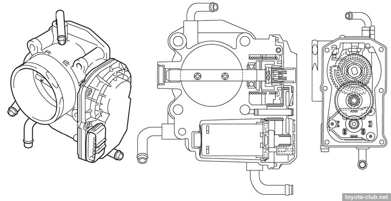
Throttle - fully electronically controlled (ETCS): DC motor, dual-channel non-contact position sensor (Hall effect). ETCS performs some functions of traction control (TRC) and stabilization (VSC).
Accelerator pedal position sensor - dual-channel non-contact (Hall effect). Camshaft position sensors - MRE type (magnetoresistive) , provide a digital output signal and work properly at low engine speed. Knock sensors - "flat" wideband piezoelectric, installed on each bank at the middle cylinder zone. Mass air flow sensor (MAF) - "hot wire" type, combined with the intake temperature sensor. Upstream - planar air-fuel ratio sensor (AFS), downstream - traditional oxygen sensor.
To reduce vibrations an active front engine mount is used (operates at speed below 900 rpm). ECM commands VSV to supply vacuum to the mount changing the pressure in the air chamber. The diaphragm vibrates and transmits vibrations through the liquid to the rubber part. So the mount internal vibration compensates engine vibration at idling. The desired frequency of vibration is regulated by selective orifices and vacuum drain hose.
Electrical Ignition system - DIS-6 (separate coil for each cylinder). Spark plugs - "iridium" (Denso FK20HR11 - central electrode of iridium alloy, side electrode of platinum), with a long threaded portion (thereby cooling channel can be expanded in the head to improve heat dissipation).
Alternator - with double segment coil and one-way clutch in the pulley (return current 100/130A). Double coil (two sets of three-phase windings with a shift of 30°) reduces electrical interference and noise at high load. One-way clutch with spring is installed between the inner and outer portions of the pulley to transmit torque only in the direction of rotation of the crankshaft, reducing the load on the drive belt. Starting system - new 1.7 kW starter with planetary gear and segment armature coil and permanent magnets instead the field coil. Auxiliary drive - by serpentine belt with automatic spring tensioner.
Early version (type'2004) have a number differences beside the rest of GR engines. • "Mono"-VVT - adjustable timing for intake only, in range of 50°.
• The cylinder heads are traditional, without camshafts carrier, without hydraulic lash adjusters.
• There are not spacer in the water jacket. • More complex crankshaft shape (9 counterweights). • More massive piston with less reduced skirt.
• The oil filter is installed at he engine top with oil cooler.
• The main cooling fan is mechanical belt driven, mounted with silicone fluid filled coupling, which is controlled by the bimetallic thermoelement, to provides a desired dependence between temperature and fan speed.
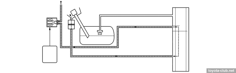
• Unusual high RON requirements even for Japanese market version (Regular - only in North America). • Some models was equipped by additional fuel tank, but simple scheme is implemented - with ejection pump and common filler, without switching system. • To control the performance of the fuel pump (3 speeds) the separate electronic control unit was installed. • The fuel system - with return line, the fuel pressure regulator - vacuum, at the intake manifold.
• At the first year of production engines inductive camshaft position sensors was installed.. • ACIS with vacuum actuator instead of the electric drive and somewhat different work algorithm..
• Spark plugs with a long threaded portion, but of conventional materials (Denso K20HR-U11, NGK LFR6C-11). • Starters - modern with a planetary gear and segment armature coil as well more powerful (2 kW) conventional with reducer (for cold climate). The second variant (type'2009) was structurally similar to other GR motors. The exhaust timing adjusting (the range is 40° for intake and 35° for exhaust), the camshaft carriers, the spacer in the cooling jacket, more compact pistons, simplified crankshaft were implemented, collapsible oil filter and oil cooler are moved to a separate bracket under the engine, more advanced spark plugs are used (Denso SK20HR11), the exhaust air injection system was applied.
Taking into account the difference in layout, 3GR MPI is substantially similar to 2GR-FE. • There is the spacer in the water jacket installed, it allows more intensive coolant circulation near the top of the cylinder, which improves heat dissipation and helps to more evenly thermally load.
• Front engine mounts are liquid filled, active mounts not applied. • The oil filter is installed horizontally in the front, on the top of upper sump bracket (the sump has a specific for longitudinal layout engines shape). The oil level sensor is installed (limit switch with a float) - if a low level is maintained for more than 40 seconds, the system switches on warning light.
• There is ATF heater in the cooling system installed. Radiator fans - electrical, controlled via a separate control unit.
• The fuel system - with return line, the fuel pressure regulator bilt in the fuel pump module.
• ACIS drive - electrical, operates by algorithm similar to 1GR-FE. Other intake geometry controls are not used.
• ETCS supports SNOW operation mode SNOW, damping response to the accelerator pedal pressing. • Spark plugs - "iridium", single-electroded (Denso FK20HR11 / NGK ILFR6D11).
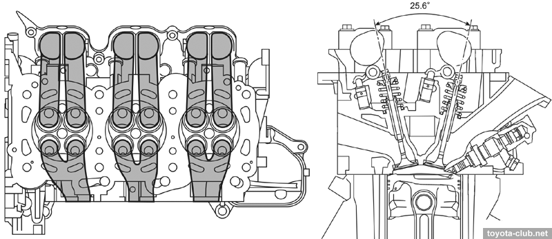
Direct injection engines have some differences at mechanical part. • The higher the compression ratio. • The fuel injectors are mounted in cylinder head. The shape of the intake port promotes the generation of "reverse swirl" in the cylinder.
• Pistons with a specific shape are different for the left and right banks.
Fuel injection system (D-4)
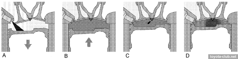
Fuel injection - direct in the combustion chamber, is synchronized with piston position. The fuel from tank pump is supplied to high pressure pump, than under pressure (4..13 MPa) into the fuel rail, and finally into the cylinders by injectors. Operation . The engine works in two basic modes: - Homogeneous mixture mode - injection during the intake stroke, the fuel mixes with air and forms a homogeneous mixture with a composition close to the stoichiometric. Due to the evaporation of injected fuel, air charge in the cylinder is cooled further reduces the possibility of knocking and improves cylinder filling.
- Stratified combustion mode - injection at the end of the compression stroke - the fuel is reflected from the recess of the piston, actively dispersed and vaporized, heading to the spark plug. Although the mixture in whole cylinder is lean, at spark plug area it is rich enough to be ignited by spark and fire the remaining volume. Lean mixture in the remaining volume is less prone to detonation, which allows to increase the compression ratio and increase engine output. Due to the evaporation of injected fuel air charge in the cylinder is cooled further reduces the possibility of knocking. This mode is used after a cold start to accelerate catalyst warm-up.
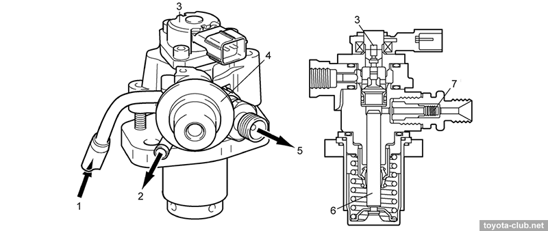
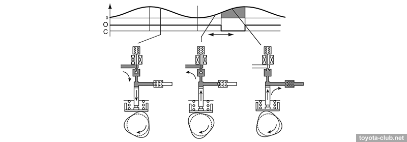
Injection/supply pump. Single-plunger with control valve, check valve and pulsation damper at inlet. Installed in the rear of the right bank valve cover, driven by exhaust camshaft additional cam. There is an insulating spacer installed between the pump and valve cover to reduce pump heat.
- At inlet stroke the plunger moves downward and fuel draws into the pumping chamber. - At the beginning of the compression stroke part of the fuel is returned while control valve is open (the specified fuel pressure is set in the range 4-13 MPa). - At the end of the compression stroke control valve is closed and the pressurized fuel through the check valve is supplied into the fuel rail. - At the engine start the control valve is opened and the fuel is fed directly into the manifold at regulator pressure (400 kPa).
Fuel rail. Made of aluminium alloy, contains fuel pressure sensor to provide feedback, and a mechanical pressure relief valve (opens the drain line to the tank if the pressure exceeds 15.3 MPa).
Injectors. Slotted nozzle injector injects the fuel into the cylinder as specific shaped spray that draws in a significant amount of air and increases the mass admission. The nozzle protruding in the combustion chamber have special non-stick coating. Sealing teflon (PTFE) rings further reduce vibration.
Injector driver (EDU). The injectors are controlled by a driver, which converts the signal from the control unit in the high-voltage signal to the injectors, ensuring maximum operation speed. After the opening of the nozzle is held opened by low voltage signal.
SCV (swirl control valve) actuator. There is SCV block between the cylinder head and the inlet manifold, which closes one of two inlets channel to each cylinder, depending on the driving conditions. Flaps are driven by electric motor via linkage.
- At low speed, low load, low coolant temperature SCV is closed, air flows through one port, that increases flow speed for better mixture combustion. - At high loads SCV is opened, air enters through both ports increases filling of cylinders, the vertical vortex in the combustion chamber created, carburetion is improved.
A great advantage of D-4 at GR series - the absence of EGR. Spark plugs. "Iridium" (Denso FK20HBR11 / NGK ILFR6D11T) - in addition to the platinum electrode contact, added two side electrodes.
With the exception of the fuel system, construction is similar to the 3GR / 4GR. Differences at the mechanical part include: - Increased range of variable timing up to 60° (intake) and 35° (exhaust). - Another type of the piston - for D-4 with a lower compression ratio.
Fuel injection system (D-4S)
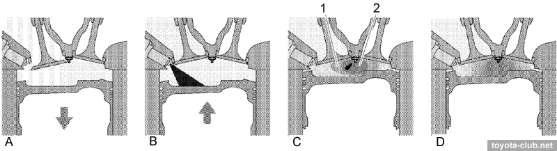
Fuel injection - combined: directly in the combustion chamber and multipoint in the inlet ports. At low to medium loads and low speeds - combined injection is applied - homogeneous mixture increases the stability of the combustion process and reduces emissions. At high load - direct injection is applied - the evaporation of the fuel in the cylinder improves the mass admission and reduces the tendency to knocking, which allows to increase the compression ratio.
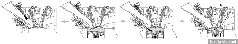
Operation modes. - Stratified combustion mode. Fuel is supplied in the intake ports on the exhaust stroke. On the intake stroke after the valves are opened a homogeneous mixture flows in the cylinder. At the end of the compression stroke, additional fuel is injected directly into the cylinder, allowing to enrich the mixture near the spark plug. This facilitates the initial ignition, is then distributed on the all lean mixture charge in the remaining volume of the combustion chamber. This mode is applied after a cold start to retard ignition timing and to increase the exhaust gas temperature for accelerate catalyst warming up.
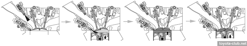
- Homogeneous mixture mode. Fuel is supplied to the intake ports on the exhaust stroke. On the intake stroke after the valves are opened a homogeneous mixture flows in the cylinder, additional fuel is injected directly into the cylinder and uniformly mixed with the incoming charge due to turbulence. Homogeneous air-fuel mixture is compressed and then ignited. Due to the evaporation of injected fuel, air charge in the cylinder is cooled improves cylinder filling.
There are some differences in direct injection system: • Pressure relief valve is electronically controlled.
• Double-slotted injector nozzles.
• For low pressure injection traditional fuel rail without the return line is provided.
Content 2GR-FE 1GR-FE / 6GR-FE 3GR-FE / 5GR-FE 3GR-FSE / 4GR-FSE 2GR-FSE 2GR-FKS Toyota engines review |
|