|
Eugenio,77
mail@toyota-club.net
© Toyota-Club.Net
Oct 2015 - Sep 2023
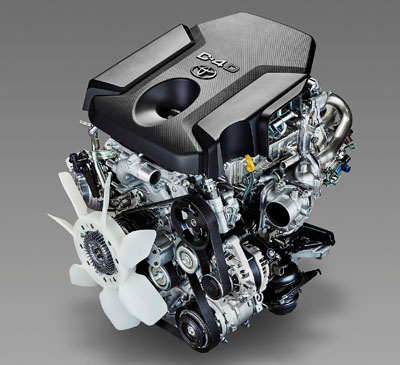
GD engines introduced at 2015 as a replacement of obsolete KD series, the most popular diesels of Toyota. Applications - Land Cruiser Prado, HiLux family (Fortuner, Innova), Hiace family (RegiusAce, Mazda Bongo Brawny). With this engine Toyota returns diesel passenger cars to the domestic market.
Updated edition - added information on the forced version 1GD-FTV type'20.
Specifications
| Engine | Displacement, cm3 | Bore x Stroke, mm | Compression ratio | Output, PS | Torque, Nm | - |
| 1GD-FTV | 2755 | 92.0 x 103.6 | 15.6 | 177 / 3400 | 450 / 1600-2400 | - |
| 1GD-FTV | 2755 | 92.0 x 103.6 | 15.6 | 151 / 3600 | 300 / 1000-3400 | low spec |
| 1GD-FTV | 2755 | 92.0 x 103.6 | 15.6 | 204 / 3400 | 500 / 1600-2800 | high spec |
| 1GD-FTV | 2755 | 92.0 x 103.6 | 15.6 | 224 / 3000 | 550 / 1600-2800 | GR sport |
| 2GD-FTV | 2393 | 92.0 x 90.0 | 15.6 | 150 / 3400 | 343 / 1400-2800 | low spec |
| 2GD-FTV | 2393 | 92.0 x 90.0 | 15.6 | 150 / 3400 | 400 / 1600-2000 | - |
* engine weight with fluids filled - 270-300 kg.
Previous diesel series KD after fifteen years of production has become obsolete for a number of parameters - economy, ecology, output, noise... and was involved in the infamous story of cracking pistons. GD engines are better in all respects, however, the expected improvement in dynamic performance did not happen - nominal torque up "disappeared" somewhere in eco-systems and eco-settings. The most noticeable advantage of new diesel - reducing the vibrations and noise. The upgrade to type'20 was beneficial - the completely indecent 0-100 an 60-110 acceleration times improved by 2-3 seconds.
Engine mechanical
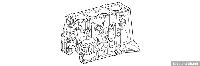
The series has retained a traditional cast-iron cylinder block without liners.
|
Note. "But local dealers advertise aluminium block with nikasil coating" - this is what you need to know about local dealers. While the official sources are available to everyone:

|
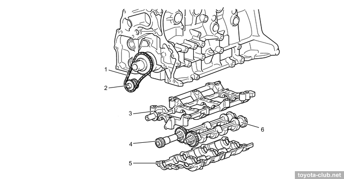
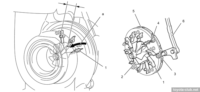
All 1GD for Prado and Hiace are equipped with balance shafts driven by chain from crankshaft. Unlike KD, balancers located in a separate case under block. For the Hilux family, balancers were not used for type'15, but appeared for type'20.
1 - chain, 2 - balancer sprocket, 3 - upper case, 4 - balance shaft 1, 5 - lower case, 6 - balance shaft 2
|
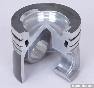
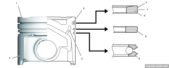
Pistons - aluminium, with full-length skirt and advanced combustion chamber.
The groove for the upper compression ring has ni-resist insert, there are cooling channel inside the piston head and friction reducing polymer coating is applied on the skirt. The upper side of piston coated with insulating coating (Toyota's designation - "SiRPA", in fact - the film of a porous anodic aluminium oxide, hardened by Perhydropolysilazane). The pistons are connected to the rods with fully floating pins.
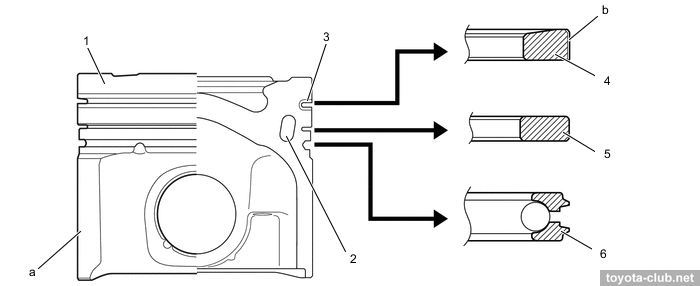
Type'15. 1 - piston, 2 - cooling channel, 3 - ni-resist cast iron ring carrier, 4 - compression ring 1, 5 - compression ring 2, 6 - oil ring. a - resin coating, b - PVD coating
|
On the '20 type, the piston shape was changed and the upper compression ring obtained an additional DLC coating.
Type'20. 1 - piston, 2 - cooling channel, 3 - ni-resist cast iron ring carrier, 4 - compression ring 1, 5 - compression ring 2, 6 - oil ring.
a - resin coating, b - PVD Coating, c - DLC Coating
|
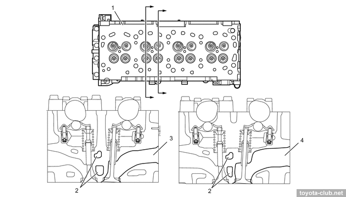
Cylinder head made of alloy. There is the tip of vertically mounted nozzle in the center of the combustion chamber and glow plug between the intake ports.
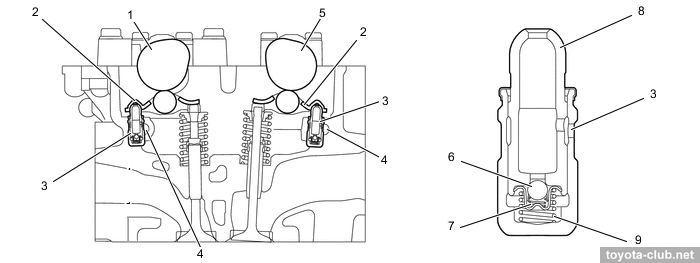
1 - exhaust camshaft, 2 - rocker arm, 3 - valve lash adjuster, 4 - oil passage, 5 - intake camshaft, 6 - check ball, 7 - spring, 8 - plunger, 9 - plunger spring
|
1 - exhaust camshaft, 2 - rocker arm, 3 - valve lash adjuster, 4 - oil passage, 5 - intake camshaft, 6 - check ball, 7 - spring, 8 - plunger, 9 - plunger spring
|
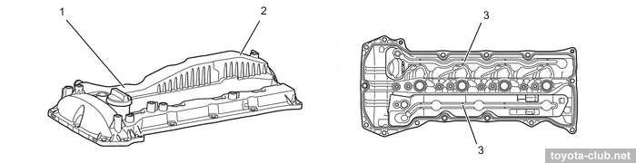
The head cover is made of plastic and provided with oil delivery pipe for the rockers lubrication.
1 - cylinder head cover, 2 - oil mist separator, 3 - oil delivery pipe
|
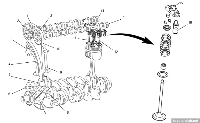
Valve mechanism - DOHC 16V: double camshafts in the head and four valves per cylinder. There are valve adjusters and roller rockers in the valve mechanism.
1 - chain 2 guide, 2 - camshaft sprocket, 3 - chain 2 tensioner, 4 - chain 2 tensioner slipper, 5 - chain 1 tensioner slipper, 6 - chain 1 tensioner, 7 - chain 1 damper, 8 - chain 1, 9 - chain 2 damper, 10 - chain 2, 11 - exhaust valve, 12 - intake valve, 13 - intake camshaft, 14 - exhaust camshaft, 15 - rocker, 16 - lash adjuster
|
There is an option for type'20 where the spring seat and the valve stem seal made integrally.
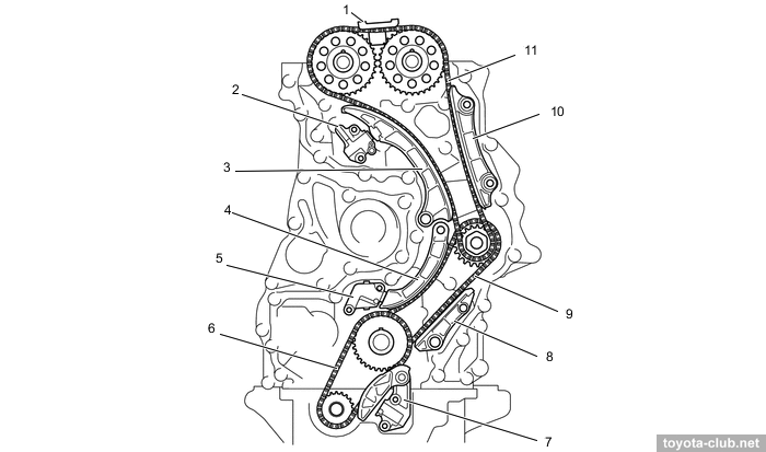
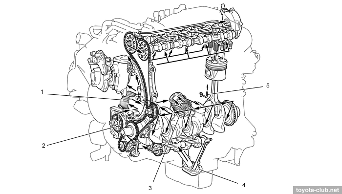
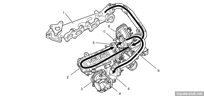
Drive is "two-step" - from the crankshaft by the primary roller chain (pitch 9.525 mm) to fuel pump shaft, and then by secondary chain (pitch 8.0 mm) to camshafts. Chain tensioned by spring enforced hydraulic tensioner with ratchet mechanism. Vacuum pump is driven by rear side of camshaft.
1 - chain 2 guide, 2 - chain 2 tensioner, 3 - chain 2 tensioner slipper, 4 - chain 1 tensioner slipper, 5 - chain 1 tensioner, 6 - balancers chain, 7 - balancers chain tensioner, 8 - chain 1 damper, 9 - chain 1, 10 - chain 2 damper, 11 - chain 2
|
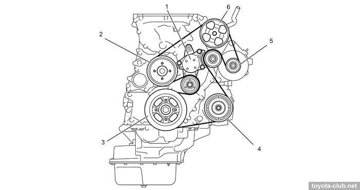
Auxiliary driven by common belt with automatic tensioner.
1 - belt tensioner, 2 - water pump, 3 - crankshaft, 4 - compressor, 5 - alternator, 6 - power steering pump
|
Vehicle could be equipped with an optional Viscous Heater.
Lubrication
Trochoid oil pump is gear driven from crankshaft. Oil cooler installed on front side of the block. Oil nozzles that lubricate and cool the piston are provided.
1 - oil cooler, 2 - oil pump, 3 - oil filter, 4 - oil strainer, 5 - oil nozzle
|
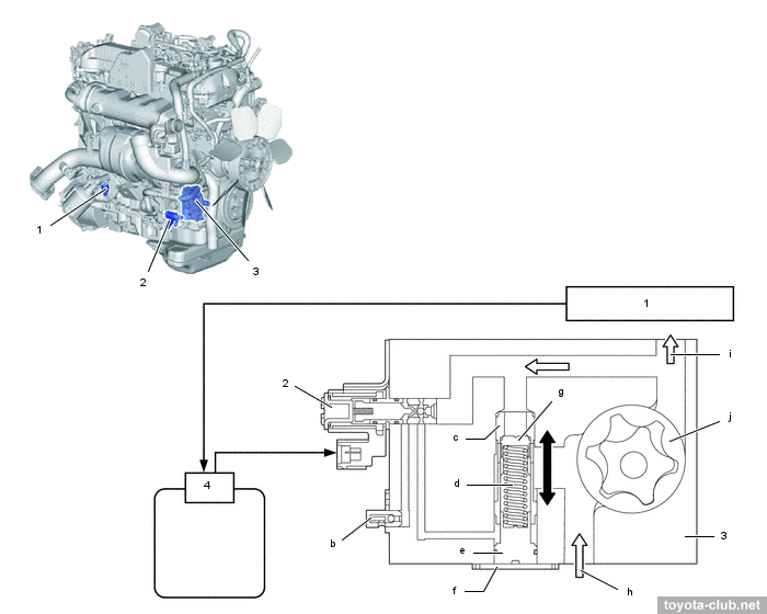
The type'20 uses a 2-stage oil pump: the valve controls a sleeve that regulates the pump relief pressure, so at high pressure mode the piston oil nozzles operate.
1 - oil pressure sensor, 2 - OSV, 3 - oil pump, 4 - ECM. b - check valve, c - sleeve, d - spring, e - guide, f - plug, g - relief valve, h - from oil pan, i - to main oil hole, j - rotor of oil pump
|
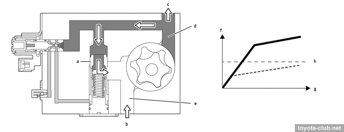
High pressure mode (valve off). Oil is not supplied to the rear of the sleeve, the sleeve is pushed down by the discharge pressure, lowering the relief hole and increasing the spring force required to open the relief valve. The opening pressure increases, increasing the discharge pressure.
a - sleeve, b - from oil pan, c - to main oil hole, d - discharge side, e -
suction side, f - oil pressure, g - engine speed, h - opening pressure of piston oil jet
|
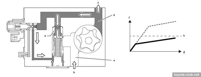
Low pressure mode (valve on). Oil is supplied to the back of the sleeve, the sleeve is pushed up by the discharge pressure, raising the relief hole position and decreasing the spring force required to open the relief valve. The opening pressure decreases, decreasing discharge pressure.
a - sleeve, b - from oil pan, c - to main oil hole, d - discharge side, e -
suction side, f - oil pressure, g - engine speed, h - opening pressure of piston oil jet
|
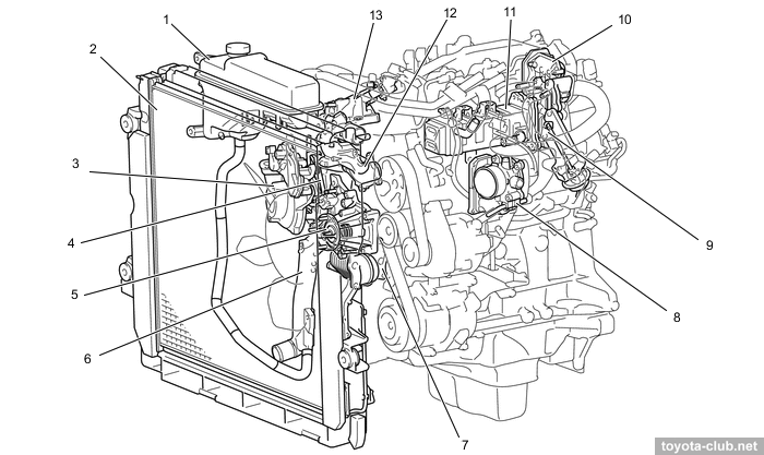
Cooling
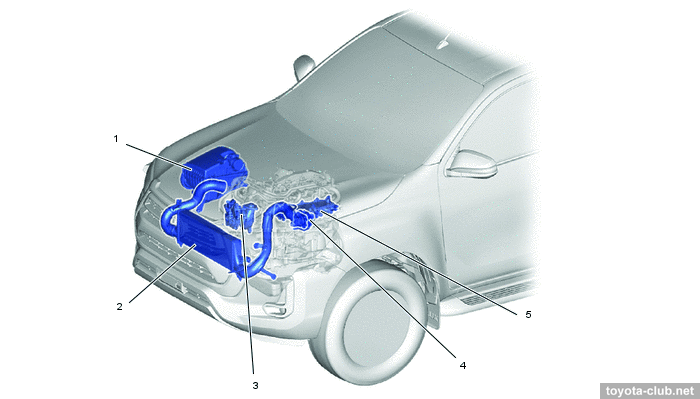
Coolant remarkable by number of components requiring cooling or heating. Pump and fan drive - by serpentine belt, thermostat - "cold" (80-84°C) mechanical.
1 - radiator reserve tank, 2 - radiator, 3 - turbocharger, 4 - turbo water pipe, 5 - thermostat, 6 - water inlet, 7 - oil cooler, 8 - diesel throttle body, 9 - EGR cooler bypass valve, 10 - EGR control valve, 11 - EGR cooler, 12 - water outlet, 13 - injector holder
|
1 - reservoir tank, 2- radiator, 3 - injector 1 holder, 4 - water outlet, 5 - turbocharger, 6 - oil cooler, 7 - aux heater, 8 - water pump, 9 - heater, 10 - turbo inlet, 11 - EGR control valve, 12 - EGR cooler, 13 - cylinder head, 14 - cylinder block, 15 - thermostat, 16 - water inlet, 17 - crankcase ventilation pipe, 18 - EGR cooler by-pass valve, 19 - throttle body
|
Intake system
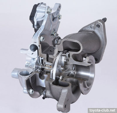
• GD engine uses turbocharger with variable nozzle (VGT or VNT) of 2nd generation (electric actuator).
Advantages - the maintenance of optimum boost pressure over a wide rev range, lowering back pressure at high speed, increased output at low speeds, no need for the bypass. Turbocharger has water cooling.
For type'20: the turbine diameter increased, a cooling circuit added to the compressor case, support ball bearings added and the VNT slightly updated.
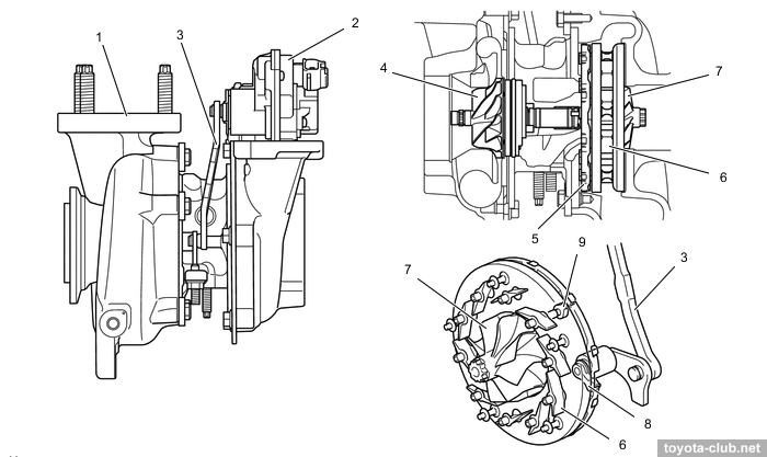
1 - turbocharger, 2 - actuator, 3 - linkage, 4 - compressor wheel, 5 - unison ring, 6 - nozzle vane, 7 - turbine wheel, 8 - drive arm, 9 - driven arm
|
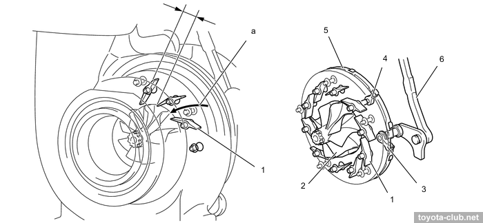
- At low load and low engine speed actuator moves the control ring and turns pivotally connected vanes to partially closed position. This increases the speed of gas entering the turbine, increases the boost pressure and increases engine torque.
1 - nozzle vane, 2 - turbine wheel, 3 - drive arm, 4 - driven arm, 5 - unison ring, 6 - linkage
|
- At high load and high speed vanes are moved to the open position, allowing maintain the desired boost pressure and reduce resistance at exhaust.
1 - nozzle vane, 2 - turbine wheel, 3 - drive arm, 4 - driven arm, 5 - unison ring, 6 - linkage
|
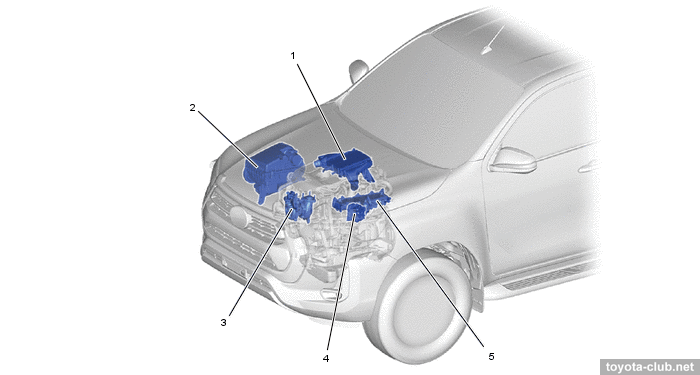
• To cool the charge air car is equipped with front-mount intercooler. The type'20 has a version with a water intercooler.
Air IC. 1 - air cleaner, 2 - intercooler, 3 - turbocharger, 4 - throttle body, 5 - intake manifold
|
Water IC. 1 - intercooler, 2 - air cleaner, 3 - turbocharger, 4 - throttle body, 5 -
intake manifold
|
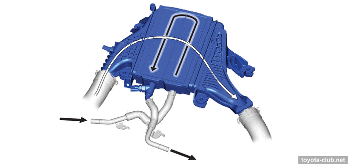
1 - intercooler. a - from intercooler cooling radiator, b - to intercooler reserve tank
|
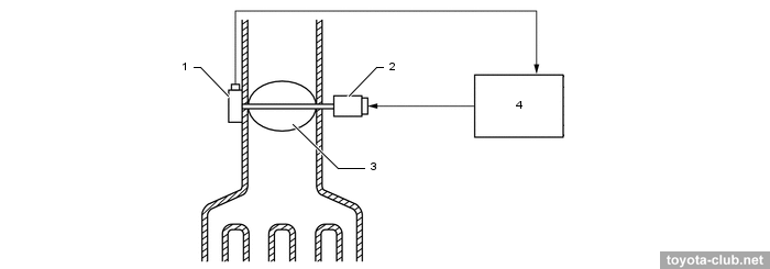
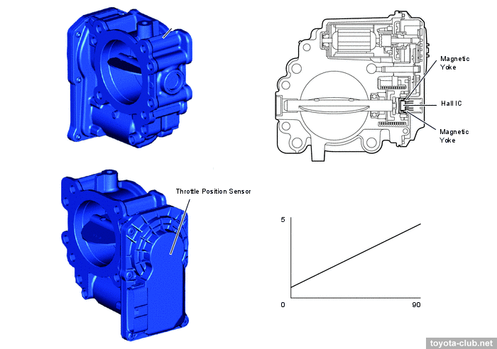
• There is the electronic controlled throttle in the intake channel. It is used to reduce the noise at idling or deceleration, and for smoother engine stop.
1 - throttle position sensor, 2 - throttle control motor, 3 - diesel throttle valve,
4 - ECM
|
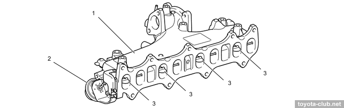
• For type'15 the pneumatically driving flaps are installed in the intake manifold to close one of the inlet ports, what forming intensive vortex in the cylinder and improve the combustion process. At type'20 the swirl control was abandoned.
1 - intake manifold, 2 - actuator, 3 - flaps
|
Fuel system / Engine control
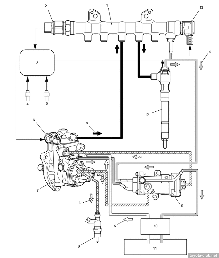
Common Rail type fuel system - the fuel is supplied by high pressure pump in a common rail and then is injected into the cylinders via the electronically controlled injectors. The injection pressure - 35-220 MPa (record for Toyota diesel). For type'20, the pressure was increased to 250 MPa. The components made by Denso.
Fuel system (type'15). 1 - common rail, 2 - fuel pressure sensor, 3 - ECM, 4 - crankshaft position sensor, 5 - camshaft position sensor, 6 - control valve (IMV/SCV), 7 - supply pump, 8 - exhaust fuel injector, 9 - pressurized fuel filter, 10 - fuel filter, 11 - fuel tank, 12 - injector, 13 - pressure discharge valve. a - high pressure, b - feed pressure, c - suction, d - return
|
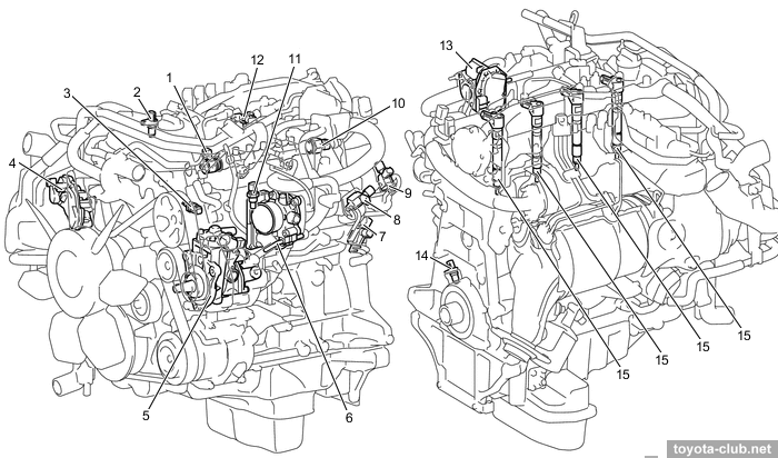
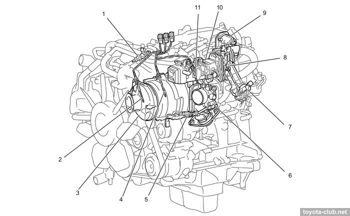
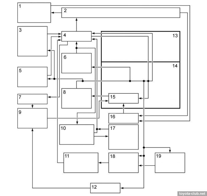
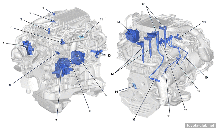
ECD (type'15). 1 - pressure discharge valve, 2 - camshaft position sensor, 3 - coolant temperature sensor, 4 - turbocharger (VGT), 5 - supply pump, 6 - throttle body, 7 - vacuum switching valve (active mounts), 8 - EGR VSV, 9 - swirl control VSV, 10 - fuel pressure sensor, 11 - air temperature sensor, 12 - turbo pressure sensor, 13 - EGR control valve, 14 - crankshaft position sensor, 15 - injector
|
|
ECD (type'20), w/ DPF and w/ SCR. 1 - intake air temperature sensor (intercooler), 2 - engine coolant temperature sensor (intercooler), 3 - cam position sensor, 4 - pressure discharge valve, 5 - turbocharger, 6 - engine coolant temperature sensor, 7 - injection pump, 8 - intake air temperature sensor, 9 - throttle body, 10 - vacuum switching valve, 11 - turbo pressure sensor, 12 - injector, 13 - EGR control valve, 14 - crank position sensor, 15 - NOx sensor 1, 16 - exhaust gas temperature sensor 3, 17 - differential pressure sensor, 18 - exhaust gas temperature sensor 2, 19 - exhaust gas temperature sensor, 20 - exhaust fuel addition injector
|
Injection can be carried out several times at the cycle: two short pilot (before TDC of the compression stroke), main (TDC of the compression stroke and the beginning of the expansion stroke), after-injection (on the expansion stroke).
Fuel pressure control carried out by supply pump control valve and by pressure discharge valve.
There are following sensors in the system:
- boost pressure
- fuel pressure
- crankshaft position (MRE)
- camshaft position (MRE)
- air flow sensor (MAF) / air temperature sensor
- throttle position (Hall effect)
- accelerator position (Hall effect)
- DPF differential pressure
- exhaust gas temperature - thermistor type, located before DOC, before DPF, after DPF, after SCR catalyst
- air-fuel ratio, after DPF
- NOx, in central exhaust pipe
• For type'20, the control system received the brand name i-ART (intelligent-Accuracy Refinement Technology).
- Instead of a fuel rail pressure sensor, the fuel pressure and temperature sensors built into the injectors.
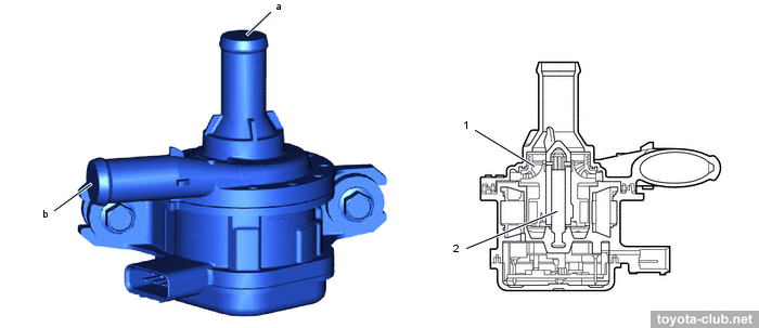
- There is a compact electric pump in the intercooler circuit.
1 - rotor, 2 - shaft. a - inlet, b - outlet
|
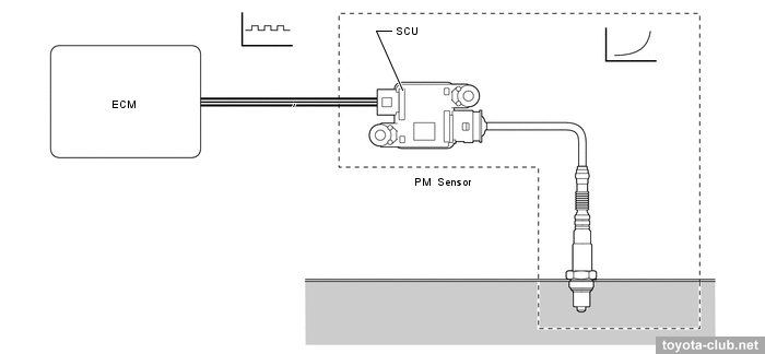
- A particle matter sensor is installed in the front exhaust pipe to monitor the condition of the DPF.
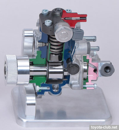
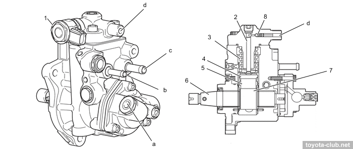
Fuel system / Supply pump
High pressure supply pump - HP5S type, consists of cam shaft, plunger, check valve, feed pump and control valve. The simpler versions without DPF have not additional low-pressure section.
1 - control valve, 2 - plunger, 3 - spring, 4 - follower, 5 - roller, 6 - camshaft, 7 - double cam, 8 - check ball. a - to exhaust fuel addition injector and pressurized fuel filter, b - fuel return port (to pressurized fuel filter), c - fuel inlet port (from fuel tank), d - to common-rail
|
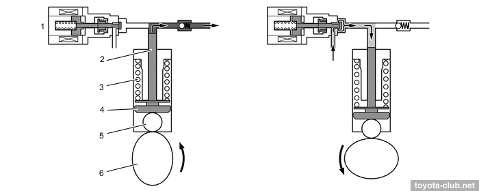
Rotating cam via follower moves the plunger upwards. If the control valve is closed, the pressure increases and the fuel from the pump flows into the rail. ECM controls the timing of control valve closing and thus provides a target level of pressure in the fuel rail. If the plunger is not pushed by cam, it is returned downward by the spring force.
1 - control valve, 2 - plunger, 3 - spring, 4 - follower, 5 - roller, 6 - double cam
|
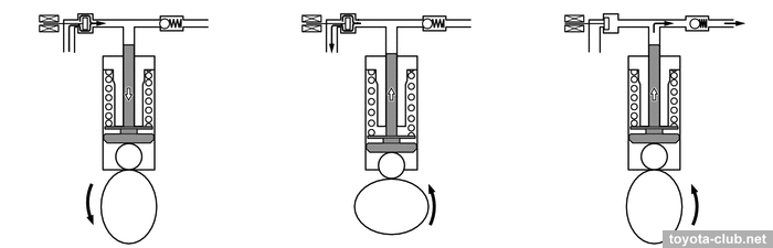
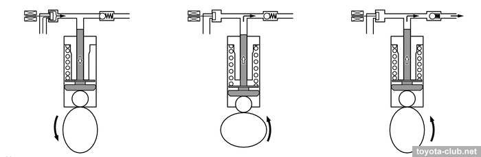
Late closing of the control valve increases fuel discharge to inlet and reduces supply volume.
Early closing of the control valve increases supply volume.
The pressurized fuel filter can be installed to provide additional protection of pump, rail and injectors.
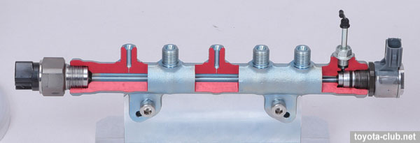
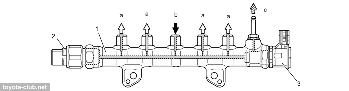
Fuel system / Rail
There are fuel pressure sensor and pressure discharge valve in the fuel rail. Electronically controlled valve opens and closes by a signal from the control unit, moreover, it can function of emergency pressure relief.
1 - common-rail, 2 - fuel pressure sensor (type'15), 3 - pressure discharge valve. a - to injector, b - from supply pump, c - to fuel tank
|
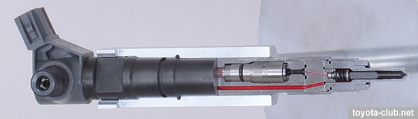
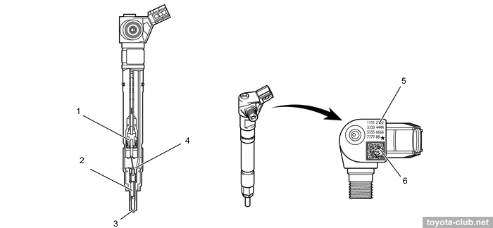
Fuel system / Injectors
• In accordance with the latest trends, GD series obtain solenoid injectors (not piezo).
Specific injector data (model code, the individual feed correction) printed as QR code and be sure to be programmed in the control unit.
1 - solenoid, 2 - needle, 3 - nozzle, 4 - control plate, 5 - compensation value, 6 - QR code
|
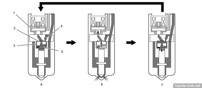
Injector operation has some difference from the previous Toyota's common rail diesels:
- When closed, the valve is held by a spring. The pressure in the control chamber is high. The fuel pressure acting on the bottom of the needle is not enough to open it.
- When the current supply to the coil, the valve opens the channel through which the fuel discharged from the control chamber. Due to pressure difference arises, the injector needle opens and fuel is injected.
- After current cut-off valve is closed. The control plate moves downward and fuel under high pressure fills control chamber and acts on top of the needle. The needle is closed and fuel injection stops. After pressure equalization in control chamber, the control plate is moved up by a spring.
1 - control valve, 2 - out-orifice, 3 - control plate, 4 - in-orifice, 5 - control chamber. a - before injection, b - injection, c - after injection
|
• The exhaust manifold has built-in low-pressure fuel injector supplied directly from the pump to raise the temperature of DPF for accumulated soot combustion.
1 - solenoid, 2 - needle valve, 3 - nozzle
|
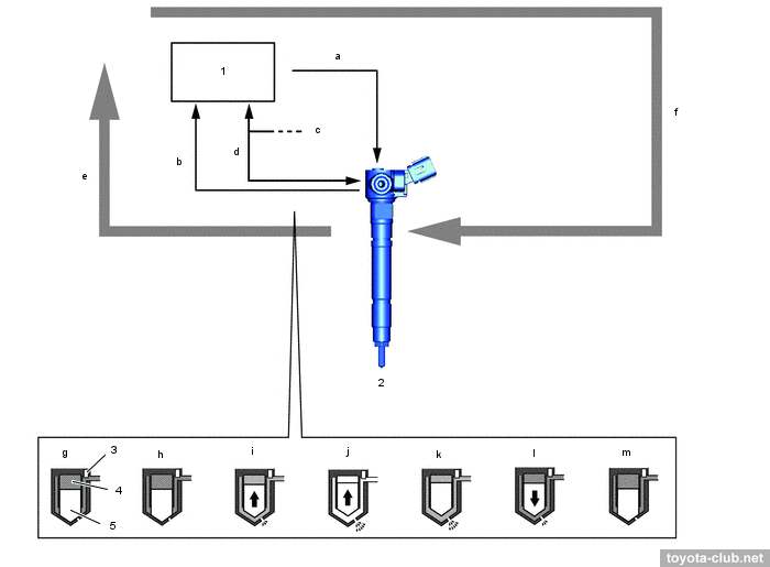
• At type'20 with i-ART, individual fuel pressure and temperature sensors allow to accurately adjust the flow injection volume of each injector, as well as to determine their malfunction (clogging or leaks). The injectors have built-in memory and even have a self-learning function.
1 - ECM, 2 - injector, 3 - fuel pressure sensor, 4 - control chamber, 5 - nozzle needle. a - operating signal, b - fuel pressure signal, c - each injector, d - injector communication (fuel temperature signal and memory ic communication), e - feedback, f - command signal, g - when there is no injection, h - when electrical current starts to flow, i - when injection starts, j - when the maximum injection rate has been reached, k - when electrical current flow has stopped, l - when the injection rate has been reduced, m - when injection has stopped
|
Emission control system
Depending on the market, there are several levels:
- EGR - Euro 2, for the third world
- EGR+DOC - Euro 4, for the third world
- EGR+DOC+DPF - Euro 5, for Australia and Russia
- EGR+DOC+DPF+SCR - Euro 6, for Europe and Japan
1 - exhaust fuel addition injector, 2 - exhaust gas temperature sensor 3, 3 - exhaust manifold converter (DOC - oxidation catalyst + DPF), 4 - exhaust gas temperature sensor 2, 5 - air fuel ratio sensor, 6 - throttle body, 7 - vacuum switching valve, 8 - EGR cooler bypass valve, 10 - EGR cooler, 11 - exhaust gas temperature sensor 1
|
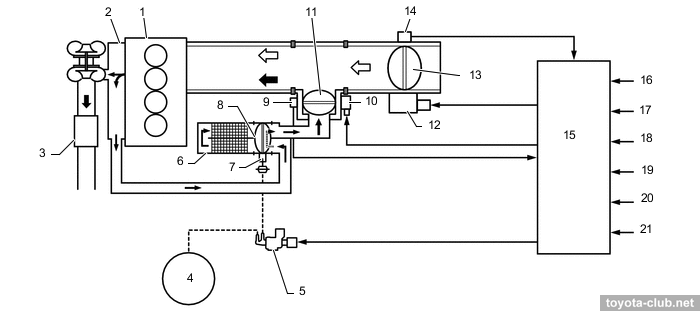
• EGR (exhaust gas recirculation) - bypass a part of exhaust gases to th intake to reduce the maximum temperature in the cylinder and reduce the nitrogen oxides emissions. EGR valve - electronically controlled, with DC motor and non-contact position sensor (Hall effect).
1 - cylinder block, 2 - exhaust manifold, 3 - DOC, 4 - vacuum pump, 5 - vacuum switching valve, 6 - EGR cooler, 7 - EGR cooler bypass valve actuator, 8 - EGR cooler bypass valve, 9 - EGR valve position sensor, 10 - EGR valve motor, 11 - EGR control valve, 12 - throttle motor, 13 - throttle valve, 14 - throttle position sensor, 15 - ECM, 16 - crankshaft position sensor, 17 - accelerator pedal sensor, 18 - coolant temperature sensor, 19 - turbo pressure sensor, 20 - air temperature sensor, 21 - air flow meter
|
To avoid excessive cooling of exhaust gases at low load, EGR cooler valve send gas flow bypass the radiator.
1 - exhaust manifold, 2 - EGR cooler, 3 - throttle body, 4 - intake manifold, 5 - EGR cooler bypass valve, 6 - EGR control valve. a - intake air, b - EGR gas, c - EGR gas (through bypass)
|
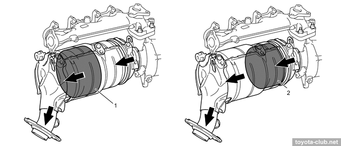
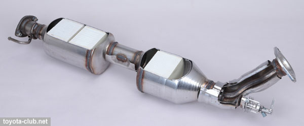
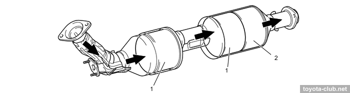
• DOC (oxidation catalyst) - primary stage of exhaust gas cleaning - oxidizes hydrocarbons (HC) and carbon monoxide (CO) to water (H2O) and carbon dioxide (CO2).
1 - DPF, 2 - DOC (oxidation catalyst)
|
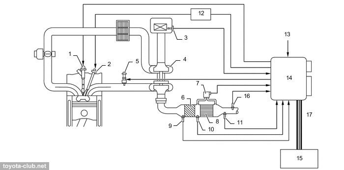
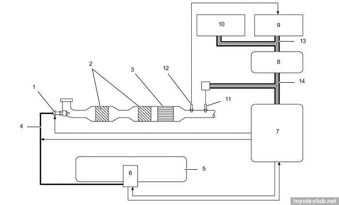
• DPF (diesel particulate filter) - used to accumulation and combustion of soot particles.
1 - injector, 2 - glow plug, 3 - air flow meter, 4 - turbocharger, 5 - exhaust fuel addition injector, 6 - oxidation catalyst (DOC), 7 - differential pressure sensor, 8 - diesel particulate filter (DPF), 9 - exhaust gas temperature sensor 1, 10 - exhaust gas temperature sensor 2, 11 - exhaust gas temperature sensor 3, 12 - glow plug controller, 13 - coolant temperature sensor, 14 - ECM, 15 - combination meter, 16 - air fuel ratio sensor, 17 - CAN bus (V)
|
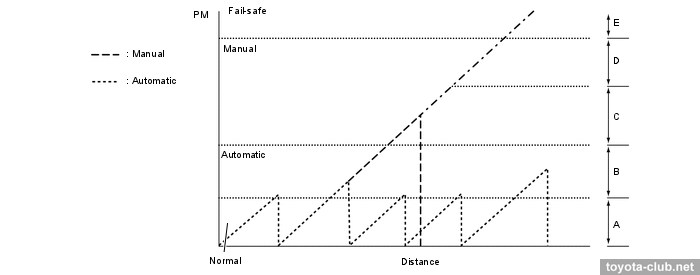
DPF passive regeneration can be performed by itself under the condition of exhaust gases high temperature.
However, over time the amount of soot in the filter is increased and its capacity is reduced which requires active regeneration. The control unit determines clogging of the filter by analysis of driving conditions, and activates injectors, the exhaust injector, glow plugs and controls the engine speed. The DPF material temperature increases up to 600-700°C and soot particles burn out.
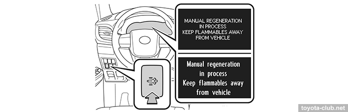
But if driving conditions do not allow to perform active regeneration automatically for a long time, soot accumulation may exceed the specified limits, so then the ECU illuminates DPF warning lamp, offering the driver to move at a constant speed above 60 km/h to perform active regeneration. When the maximum level of soot accumulation exceeded the warning lamp flashes, offering the driver to go to the workshop to perform regeneration in the manual mode. Finally, in order to avoid damage to the DPF, ECU activates fail-safe mode with limited power output.
A switch for DPF manual mode regeneration was initially offered as an option.
C - "DPF FULL MANUAL REGENERATION REQUIRED SEE OWNER'S MANUAL", D - "DPF FULL VISIT YOUR DEALER", E - MIL + "DPF FULL VISIT YOUR DEALER"
|
• SCR (selective catalytic reduction) - used to reduce of NOx contents in the exhaust gas for Euro 6 emission standards by the injection of urea solution.
After injection of the solution the water vaporizes, then urea dissociates into isocyanic acid and ammonia by hydrolysis.
CO(NH2)2 > NH3 + HNCO
At high temperature the isocyanic acid in its turn dissociates to carbon dioxide and ammonia by hydrolysis.
HNCO + H2O > NH3 + CO2
Ammonia accumulates in the catalyst and reacts with nitrogen oxides of exhaust gases, resulting in a pure nitrogen and water.
NO + NO2 + 2NH3 > 2N2 + 3H2O
1 - urea injector, 2 - SCR catalyst, 3 - ammonia slip catalyst (ASC), 4 - urea tube/heater, 5 - urea tank, 6 - urea pump, 7 - urea pump control unit, 8 - central gateway ECU, 9 - ECM, 10 - combination meter, 11 - NOx sensor, 12 - exhaust gas temperature sensor 4, 13 - CAN bus 2, 14 - CAN bus L
|
1 - SCR catalyst, 2 - ASC-catalyst
|
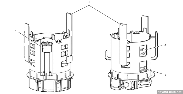
The urea solution is supplied by a multifunctional module in the lower part of the AdBlue tank. The pump delivers the solution under a pressure of about 500 kPa to the urea injector (feedback is carried out by a pressure sensor). The heater maintains the liquid state of the solution at negative temperatures (feedback is carried out by the temperature sensor in the pump). Filter and solution level sensor are provided.
|
1 - float sensor, 2 - filter, 3 - pump motor, 4 - heater
|
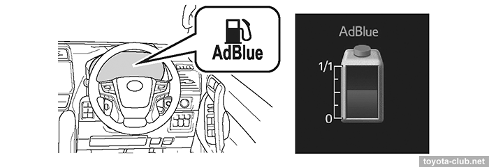
The AdBlue consumption, which is proportional to the NOx content in the exhaust gases, depends primarily on the engine load. The average consumption is declared 1 liter per 600-700 km of mileage. The volume of the urea tank is 12-14 l (LC150-Hilux). When the remaining AdBlue is enough for 2400 km mileage, the low level indicator turns on; when the remains enough for 800 km, a warning about engine start appears. When AdBlue is depleted, the engine runs, but cannot be restarted, and requires to top up at least 6.5 (LC150) or 9 (Hilux) liters of fluid.
Electrical equipment
The starting system provides a range of planetary gear starters from 1.9 to 2.7 kW. For models with stop-start function, an ATF electric pump has been added.
Engine mounts
Engines for Prado equipped with active mounts to adjust damping force.
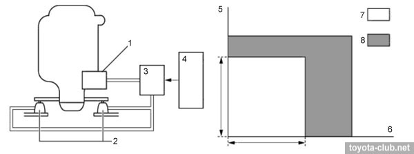
1 - vacuum pump, 2 - active mounts, 3 - VSV, 4 - ECM, 5 - vehicle speed, 6 - engine speed, 7 - valve ON, 8 - valve OFF.
|
- With the engine running at idle and vehicle low-speed, vacuum from the pump supplied by VSV to the diaphragm, which moves and opens additional channels for the fluid inside the mount. This allows more efficient damping of engine vibrations.
- Except idling, ECM switches VSV removing the vacuum from diaphragm. So the fluid circulates only through one channel with a relatively large resistance.
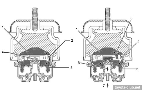
1 - chamber 1, 2 - channel 1, chamber 2, 4 - diaphragm, 5 - channel 2, 6 - diaphragm (pulled), 7 - vacuum.
|
2GD-FTV type'20
The minor engine was also modified, but minimal changes did not lead to a change of its performance: by analogy with 2.8, pistons and rings were updated, a 2-mode oil pump was installed.
The first years of operation did not reveal any major problems of the GD series, although some specific malfunctions should be noted. Moreover, these faults were unusually promptly confirmed by Toyota and described in TSB.
• [01] Difficulties of auto-regeneration cause clogging of the particulate filter. As a result, an invitation to visit a dealer is displayed and code P2463 stored. At the spring of 2017 a more successful ECU calibration appeared, since the summer of 2018 the manual regeneration button became the standard equipment, since the spring of 2019 a special kit is recommended for installing the manual regeneration button for everyone. Described in TSB EG-0026T-0416 and EG-00160T-TME.
• [02] Dust ingress in the intake duct downstream of the air filter. The result - MAF sensor contaminating, power loss and other errors. The defect is not recognized by the manufacturer, but the phenomenon is indirectly mentioned in the TSB (EG-00119T-TME).
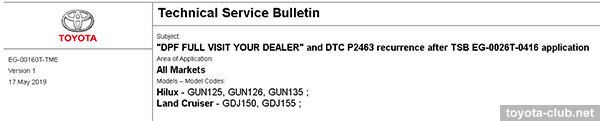
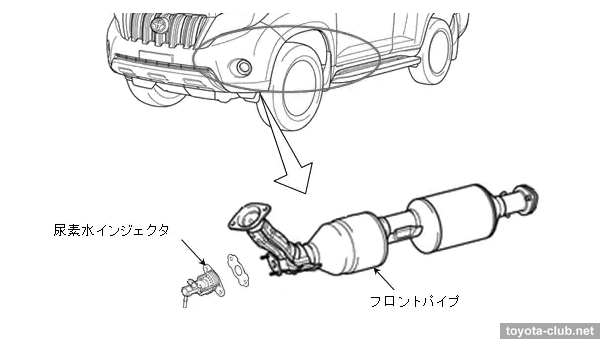
• [03] At early cars with SCR, the flange of the AdBlue injector collapsed due to corrosion. Prescription - replace the front exhaust pipe assembly. Described in recall # 4035 (13.04.2017).
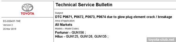
• [04] Malfunction or destruction of glow plugs, DTC P0671-P0674 stored. It is prescribed to replace the glow plugs with the modified ones, reprogram ECU and, if neccesery, check the combustion chamber for damage by broken plug tip fragments (also check turbine wheel and nozzle vanes). Described in TSB EG-00043T-TME.
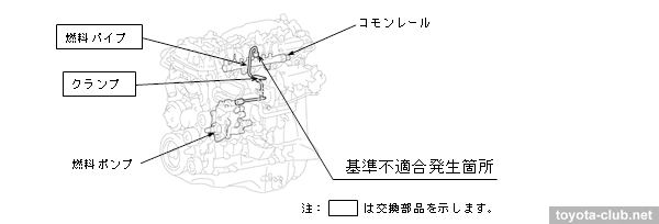
• [05] Service campaign is declared for Japan-made Land Cruiser Prado, Hiace, Regius Ace produced in March-June 2019 and equipped with 1GD-FTV engines (campaign UGG45, TSB 19SMD-064 / recall # 4571). Defect - incorrect tightening torque of the fuel pipe between the high-pressure fuel pump and the common rail, which cause loosenses of the pipe fastening and fuel leakage. Prescription - replace the fuel pipe and clamp.
• [06] DTC P24B1, P24B0, P24C6 appear due to a malfunction of the PM sensor. Prescription - replacement of the sensor and recalibration of the control unit. Described in TSB EG-00351T-TME.
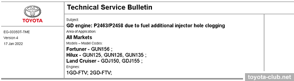
• [07] DTC P2463/P2458 appear due to fuel additional injector hole clogging. Presription - replacement of the injector holder and recalibration of the control unit. Described in TSB EG-00350T-TME (v4 17.01.2022).
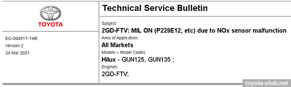
• [08] DTC P229E12 appears due to a malfunction of the NOx sensor. Prescription - replacement of the sensor and reprogramming of the control unit. Described in TSB EG-00491T-TME (27.11.2020).
• [09] DTC P24C601,P24AE14 appear due to a malfunction of the PM sensor. Prescription - replacement of the sensor (894A0-71010) and reprogramming of the control unit. Described in TSB EG-00497T-TME (08.12.2020, upd. 27.09.2022) for Hilux w/ 2GD-FTV.
• [10] The new oil pump type'20 started with a problem - MIL on and DTC P052477 appears (low oil pump pressure). The solution is simplest - reprogram the control unit to change the pressure threshold for the code detection. Described in TSB EG-00545T-TME (15.04.2021).
• [11] Phantom codes P023A* (intercooler pump) appear due to water ingress into the engine compartment main wiring harness (Hilux, TSB BE-00566T-TME, 17.06.2021).
• [12] Power loss during driving due to boost pressure sensor hose disconnected - install a clip (LC150, EG-00588T-TME, 14.07.2021).
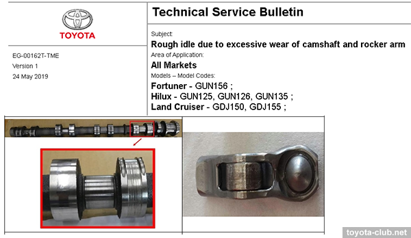
• [13] Excessive wear of camshafts and rocker arms. A possible external symptom - rough idling. It is prescribed to replace camshafts and replace all rockers with the modified ones (in 2019 two revisions of parts released). Described in TSB EG-00162T-TME.
• [14] DTC P24B1,P24B0,P24C6 appear due to a malfunction of the PM sensor. Prescription - replacement of the sensor (894A0-60010) and reprogramming of the control unit. Described in TSB EG-00351T-TME (05.10.2021, upd. 04.10.2022) for Land Cruiser w/ 1GD-FTV.
• [15] Coolant level drops, possible engine overheat due to EGR cooler internal leakage (cracks because of fatigue). Prescription - replacement of the EGR pipe with cooler (25601-11070 ⇒ 25601-35090). Described in TSB EG-00635T-TME (10.11.2021, upd. 15.03.2022) for Land Cruiser GDJ15# w/ 1GD-FTV.
• [16] Occurrence of DTC P200200/P246300/P200C4B, etc. due to abnormal fuel spray of injector. The reason is corrosion and/or deposits on the injector nozzle. Production change - new coating application on the nozzle by atomic layer deposition method. The prescription is a complex multi-stage algorithm of replacements and reprogramming, among other it includes the replacement of injectors (23670-19075⇒23670-19085, 23670-09460⇒23670-09500, 23670-09470⇒23670-09510). Described in TSB EG-00605T-TME (20.01.2022) for Hilux and Land Cruiser with 1GD-FTV/2GD-FTV.
• [17] Unstable idling at engine cold starting. Described in TSB EG-00774T-TME (19.07.2022)
• [18] DTC P202D7A - Urea pump: wrong detection due to Adblue freezing. Described in TSB EG-00789T-TME (12.10.2022)
• [19] Recall 5322 (26.05.2023, Hiace GDH2##). SCR line heater wiring is not properly processed and secured, which may cause the wiring to break due to vibration during driving.
• [20] Engine components damaged due to the EGR Valve Assy No. 2 screws detachment. Described in TSB EG-01004T-TME (14.09.2023)
|
Toyota engines review
·
AZ ·
MZ ·
NZ ·
SZ ·
ZZ ·
AR ·
GR ·
KR ·
NR ·
ZR ·
AD ·
GD ·
ND ·
VD ·
A25.M20 ·
F33 ·
G16 ·
M15 ·
T24 ·
V35 ·
|
|
|