|
Eugenio,77
mail@toyota-club.net
© Toyota-Club.Net
Aug 2020 - Feb 2022
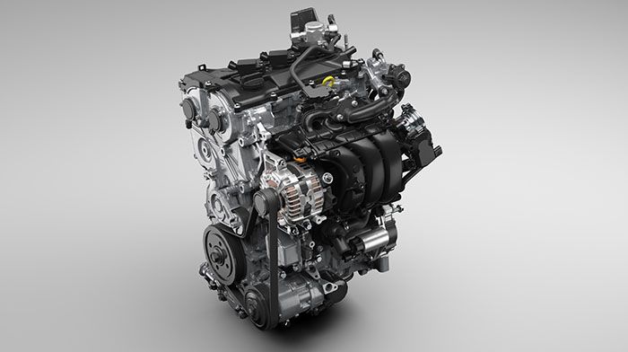
Detailed review of the features of the all-new 3-cylinder Toyota engines in two versions - D-4 for pure gasoline models and MPI for hybrids. As well as the first failures and operation experience.
| Engine | Displacement, cm3 | Cylinder bore x Piston stroke, mm | Compression ratio | Power, PS | Torque, Nm | RON | ECS |
| M15A-FKS | 1490 | 80.5 x 97.6 | 14.0 | 120 / 6600 | 145 / 4800-5200 | 91 | D-4 |
| M15A-FXE | 1490 | 80.5 x 97.6 | 14.0 | 91 / 5500 | 120 / 3800-4800 | 91 | EFI |
Compliance with eco-standards: EURO 4..6b..6d
Dry weight: 85.1 (D-4) / 87.3 (EFI)
Firing order: 1-2-3
M15A-FKS (1.5) - D-4 direct injection, DVVT-iW, Miller cycle operation mode
M15A-FXE (1.5) - for hybrids, EFI multipoint injection, DVVT-iE, Miller cycle operation mode
M15D-FXE - localized version for India (TIEI)
M15B-FKS, M15C-FKS - localized versions for China (FAW-FTCE, GAC-GTE)
"It is with a heavy heart that I take up my pen to write these" - one way or another, we have to note Toyota's another step on the path of degradation - three cylinders are appropriate for kei-cars, somehow acceptable in the 1-liter class, but such a replacement for NZ and NR series...
Officially, it is explained by layout considerations - the ratio of the diameter and stroke of the piston allows to make a three-cylinder engine a little more compact than a four-cylinder with the same displacement.
Engine mechanical - Block
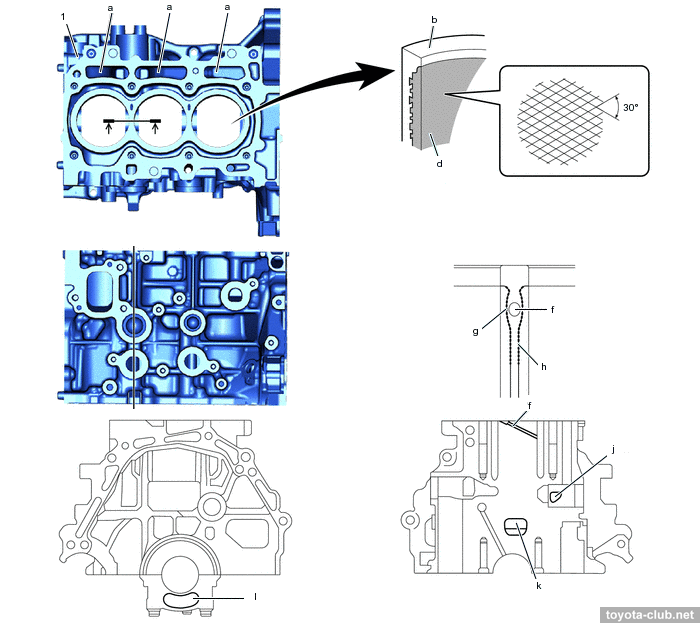
The cylinder block - aluminum "open deck" with thin cast iron liners. The liners are fused into block and their special rough outer surface provides strong connection.
Channels for oil and antifreeze are brought together for better heat transfer - fast warming up of a cold engine and cooling under high load. There are sloping coolant channels drilled between the cylinders.
1 - cylinder block. a - oil drain passage, b - cylinder bore, c - cross hatch, d - liner, f - water passage, g - cylinder liner circumference processing, h - thermal spray aluminum coating, j - fresh air introduction hole for pcv, k - larger breather hole, l - side groove
|
There is the spacer in the water jacket installed, it allows more intensive coolant circulation near the top of the cylinder, which improves heat dissipation and helps to more evenly thermally load.
The massive alloy crankcase mounted to block also performs the function of the sump upper part.
1 - crankcase, 2 - oil pan. a - oil passage, b - oil drain passage, c - oil filter bracket, d - rib, e - rear end plate, f - rear oil seal retainer.
|
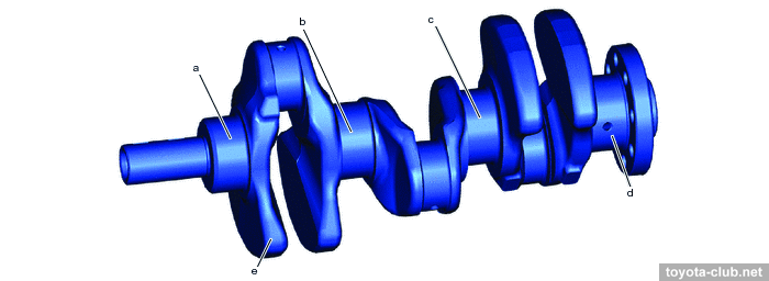
The axis of the crankshaft has been shifted by 10 mm relative to the cylinder axis lines ("desaxage"), thus reducing the lateral component of the force exerted by the piston to the cylinder wall, reducing wear.
The crankshaft has 4 balance weights, narrow journals and traditional main bearing caps. The connecting rod upper end have been "cut" to reduce weight.
a-d - journal, e - balance weight
|
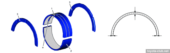
The crankshaft bearings are resin coated. The groove in the bearing is variable in depth to reduce oil drip.
1 - upper main bearing, 2 - lower main bearing, 3 - upper crankshaft thrust washer. a - oil groove
|
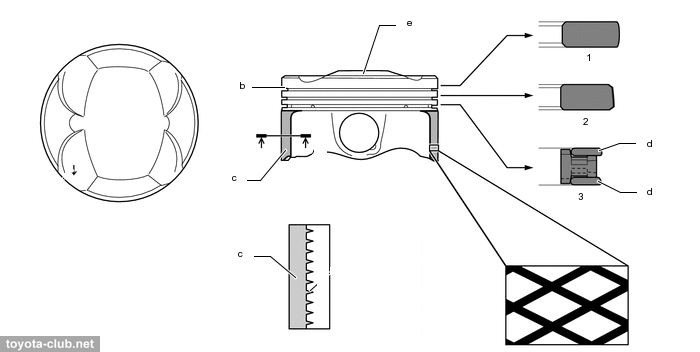
The pistons made of light-alloy, T-shaped, lightweight. The groove of the upper compression ring has alumite coating, the oil rings has anti-wear carbon coating (DLC - "diamond like"). The working part of the skirt is polymer coated. The pistons are connected to the rods with fully floating pins.
1 - upper compression ring, 2 - lower compression ring, 3 - oil ring. b - alumite coating, c - resin coating, d - DLC coating, e - combustion bowl
|
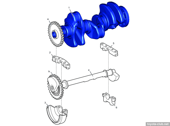
The balancer shaft is driven directly from the crankshaft via a polymer gear. The shaft with supports assembly is bolted to the crankcase for ease of maintenance.
1 - crankshaft, 2-3,5-6 - balancer shaft housing, 4 - balancer shaft. a - drive gear, b - driven gear (resin)
|
The engine has a high geometric compression ratio, although it would be more accurate to say "expansion ratio" - the actual compression ratio for Miller cycle is much lower, so the engines are designed for low octane gasoline (RON 91 / Regular).
Engine mechanical - Cylinder head
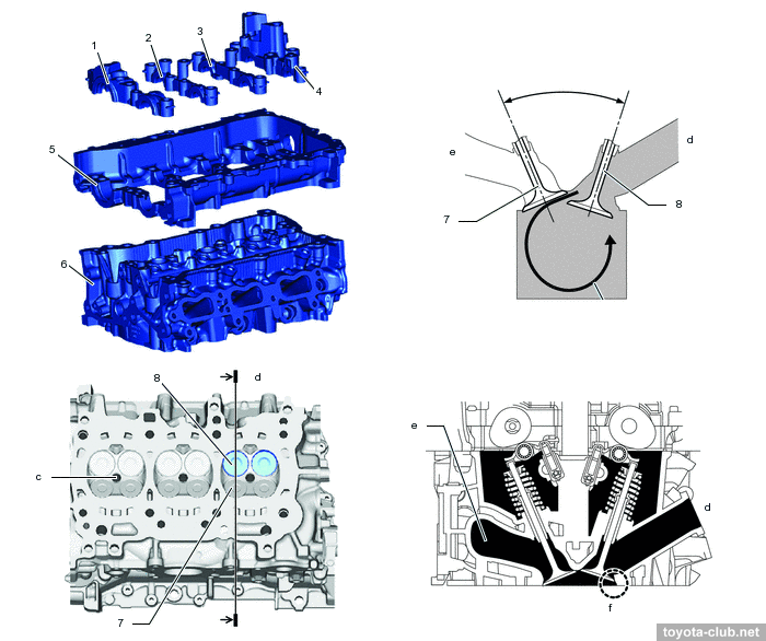
The camshafts are installed in a separate housing, which mounted on the cylinder head - it simplifies the design and manufacturing technology, however, another joint of parts has appeared requiring sealing.
1-4 - camshaft bearing cap, 5 - camshaft housing, 6 - cylinder head, 7 - exhaust valve, 8 - intake valve. c - spark plug hole, d - intake side, e - exhaust side, f - laser cladded valve seat.
|
Instead of traditional (pressed) for the inlet valves special "laser-clad" seats are used. They are much thinner than usual, providing better cooling of the valves and optimization of the ports shape and size.
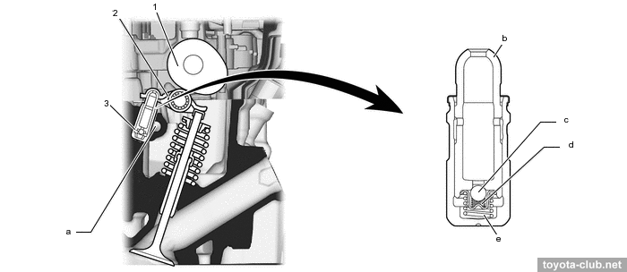
There are valve adjusters and roller rockers in the valvetrain mechanism.
1 - cam, 2 - rocker arm, 3 - valve lash adjuster. a - oil passage, b - plunger, c - check ball, d - check ball spring, e - plunger spring
|
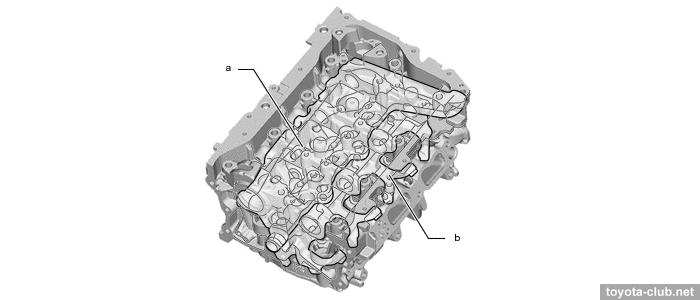
The cooling jacket of the head is divided into two levels to accelerate the flow of antifreeze.
a - upper jacket, b - lower jacket
|
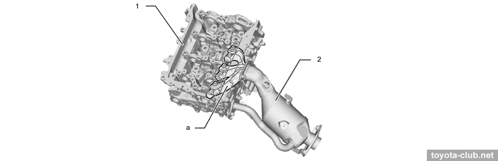
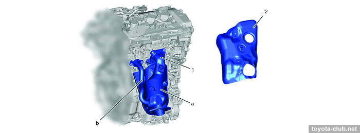
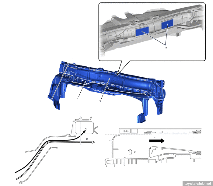
The exhaust ports of all cylinders are combined inside the cylinder head to an "integrated manifold". Optimizing the size of the exhaust ports should help to cool the exhaust gases. The EGR channel passes directly through the head.
1 - cylinder head, 2 - exhaust manifold. a - exhaust port
|
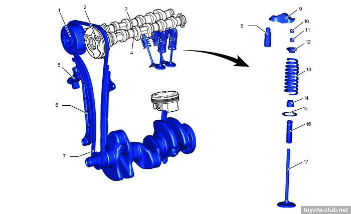
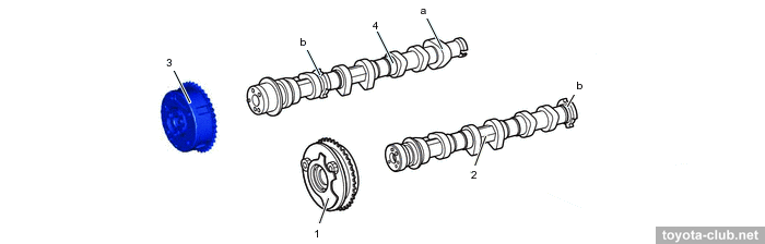
Timing drive - by single-row roller chain (pitch 8 mm) with hydraulic tensioner.
VVT actuators both on the inlet and outlet camshafts are installed (DVVT - Dual Variable Valve Timing). The actuators - hydraulic type, wide range for intake (VVT-iW), traditional for exhaust (VVT-i). Timing variations range - 70° for intake and 41° for exhaust. More about Toyota VVT operation.
1 - camshaft timing gear (exhaust), 2 - camshaft timing gear (intake), 3 - exhaust camshaft, 4 - intake camshaft, 5 - chain tensioner, 6 - chain tensioner slipper, 7 - timing chain, 8 - valve lash adjuster, 9 - rocker arm, 10 - valve stem cap, 11 - valve spring retainer lock, 12 - valve spring retainer, 13 - valve spring, 14 - valve stem oil seal, 15 - valve spring seat, 16 - valve guide bush, 17 - valve
|
The camshafts are cast iron. The exhaust camshaft drives the injection pump by profiled cam and also drives the vacuum pump.
1 - camshaft timing gear (intake), 2 - intake camshaft, 3 - camshaft timing gear (exhaust), 4 - exhaust camshaft. a - cam (fuel pump), b - timing rotor
|
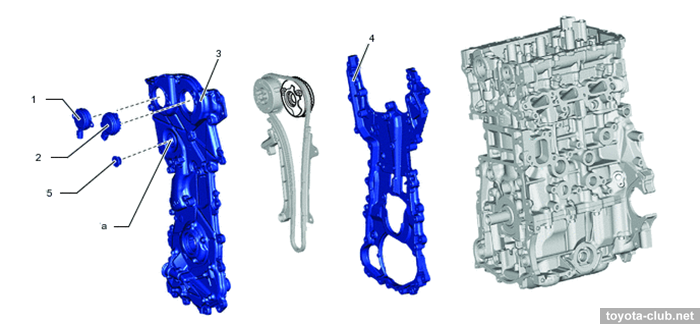
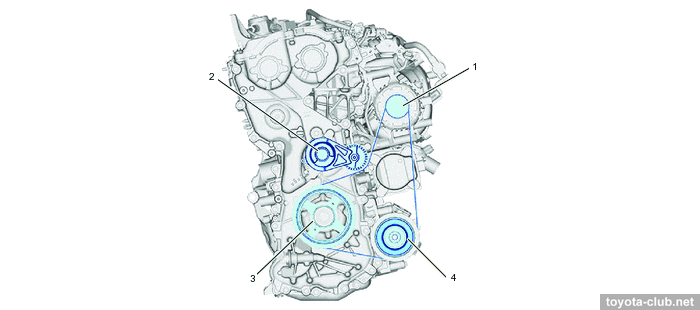
The timing chain is closed with two alloy covers (VVT-iW and VVT-i valve are attached to the front cover).
1 - VVT solenoid (exhaust), 2 - VVT solenoid (intake), 3 - front cover, 4 - rear cover, 5 - plug. a - service hole
|
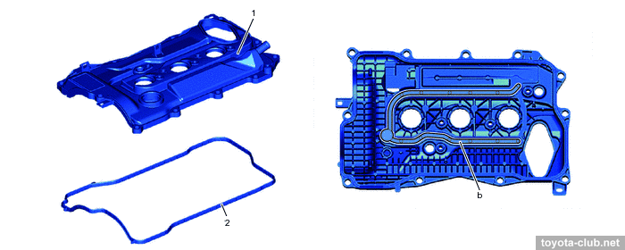
The cylinder head is covered with alloy cover, provided with oil delivery pipe for the rockers lubrication.
1 - cylinder head cover, 2 - gasket. b - oil channel
|
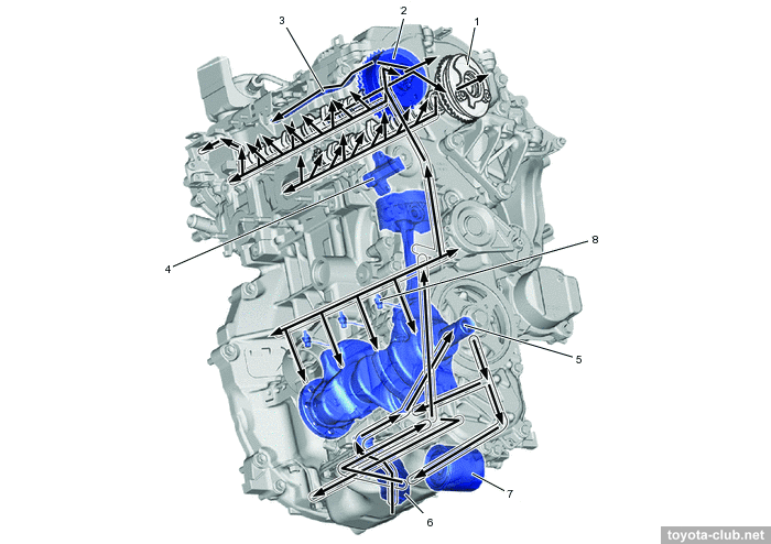
Lubrication
1 - VVT solenoid (VVT-iW), 2 - VVT solenoid (VVT-i), 3 - oil delivery pipe, 4 - chain tensioner, 5 - oil pump, 6 - oil strainer, 7 - oil filter, 8 - oil nozzle
|
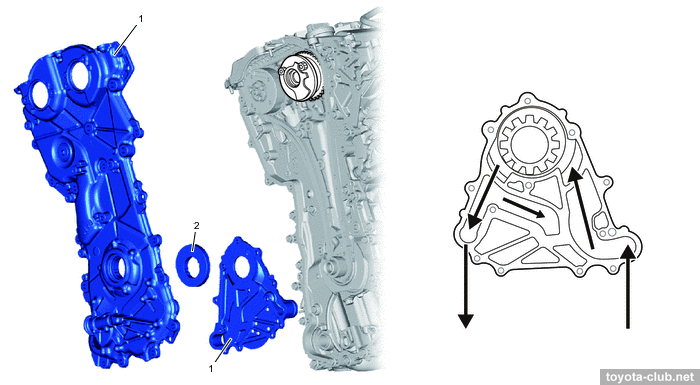
Oil pump is of traditional design, built into the chain cover and driven directly by the crankshaft.
1 - timing chain cover 2, 2 - oil pump rotor
|
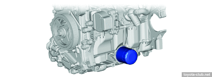
A normal spin-on type oil filter is used, mounted horizontally at the front side.
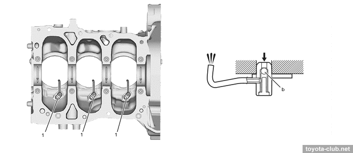
Oil nozzles that lubricate and cool the pistons are provided, supplied through check valves.
1 - oil jet. b - check valve
|
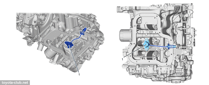
Oil level sensor is installed in the crankcase (functionally, a low-level switch).
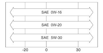
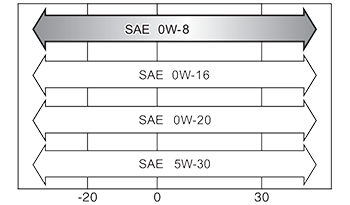
Officially prescribed oil viscosity:
Cooling
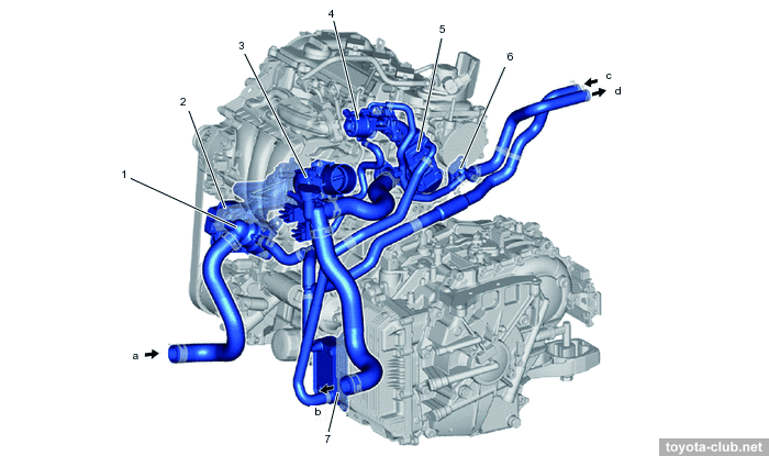
1 - water inlet with thermostat, 2 - water pump, 3 - throttle body, 4 - 4 - EGR valve, 5 - EGR cooler, 6 - water by-pass outlet, 7 - transmission oil cooler. a - from radiator, b - to radiator, c - from heater radiator, d - to heater radiator
|
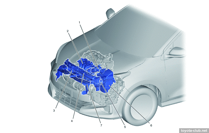
Cooling system of a new type - with an electric pump and electric thermostat, but without shut-off valves (unlike 2.0-2.5 engines).
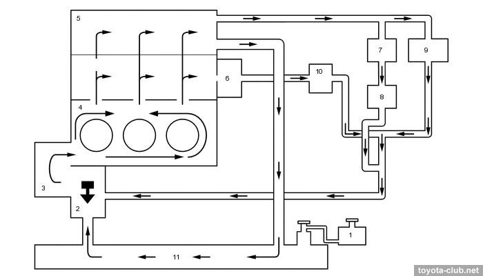
1 - reserve tank, 2 - water inlet with thermostat, 3 - water pump, 4 - cylinder block, 5 - cylinder head, 6 - EGR cooler, 7 - EGR valve, 8 - throttle body, 9 - heater radiator, 10 - transmission oil cooler, 11 - radiator. a - upper water jacket, b - lower water jacket
|
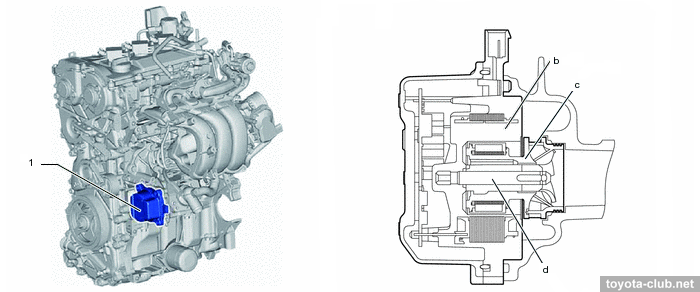
Electric pump allows to adjust the coolant flow at the discretion of ECM.
1 - water pump. b - stator, c - rotor, d - shaft
|
The nominal temperature of the thermostat opening is 80-84°C (excellently "cold engine").
The current supply to the thermostat heater allows to increase its opening under significant load conditions, lowering the temperature in advance and providing higher power output without the risk of detonation.
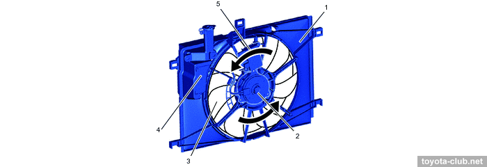
The fan motor control unit allows to adjust fan speed steplessly depending on the coolant temperature, climate control, vehicle speed and engine speed. The fan - single, large diameter.
1 - fan shroud, 2 - fan motor, 3 - fan, 4 - reserve tank, 5 - fan ECU
|
Intake and exhaust
The utmost simplicity (due to the exhaust ports connected inside the cylinder head) of the steel exhaust manifold is disturbed only by the EGR pipe.
1 - exhaust manifold, 2 - heat insulator. a - TWC, b - EGR passage
|
There are not any variable-geometry-intake devices, the electronic throttle valve (ETCS-i) is quite traditional. The only unusual thing is a pack of intake air ducts - few cleaners, inserts of non-woven material to reduce resonance noise, bends of the air flow to prevent water and snow ingress.
1 - air cleaner hose, 2 - intake manifold, 3 - radiator upper support, 4 - inlet air cleaner 2, 5 - inlet air cleaner 1, 6 - air cleaner, 7 - radiator upper air guide plate
|
1 - front upper radiator support, 2 - inlet air cleaner 2. a - pet non-woven fabric, d - air, e - water or snow
|
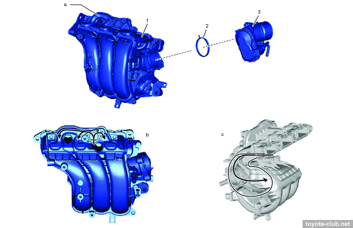
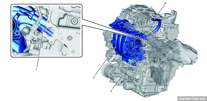
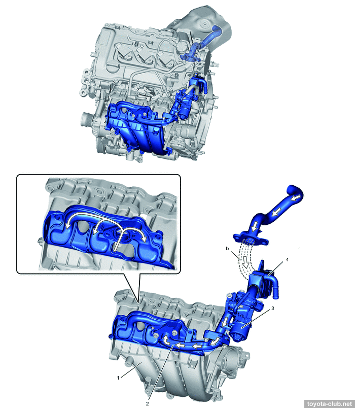
EGR collector is integrated in the plastic intake manifold and distributes the exhaust gases evenly among the cylinders.
1 - intake manifold, 2 - gasket, 3 - throttle body. a - EGR delivery, b - EGR gas flow, c - blowby gas flow
|
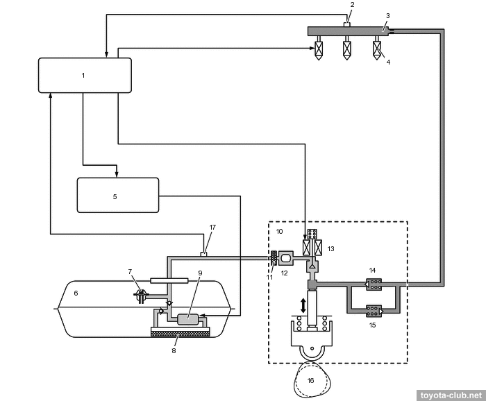
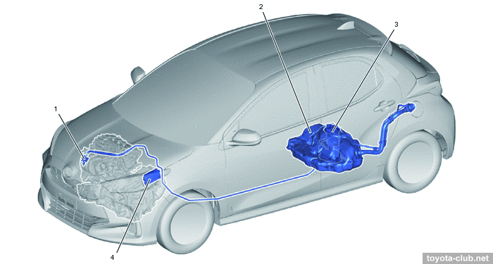
Fuel system / Engine control (D-4)
1 - ECM, 2 - fuel pressure sensor (high pressure), 3 - fuel rail, 4 - fuel injector, 5 - fuel pump ECU, 6 - fuel tank, 7 - fuel main valve, 8 - fuel filter, 9 - fuel pump (low pressure), 10 - fuel pump (high pressure), 11 - fuel sub-filter, 12 - fuel pressure pulsation damper, 13 - spill control valve, 14 - check valve, 15 - fuel relief valve, 16 - exhaust camshaft, 17 - fuel pressure sensor (low pressure)
|
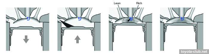
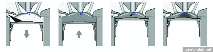
Fuel injection - direct, into the combustion chamber. There are two main modes of operation:
- Stratified combustion mode. Fuel is supplied at the end of the compression stroke, forming a charge of varying enrichment. This mode is used after a cold start, allowing to effectively ignite a lean (up to about 16:1) mixture, providing a higher combustion temperature to accelerate warm-up of the catalyst.
- Homogenous mixture mode. Fuel is supplied at the beginning of the intake stroke and is evenly mixed with the incoming air. Homogeneous air-fuel mixture is compressed and then ignited. Due to the evaporation of injected fuel, air charge in the cylinder is cooled improves cylinder filling.
Fuel pump (low pressure) delivers fuel from the tank to the injection pump. The pump control unit performs stepless adjustment of the pump speed, providing the required amount of supply. An additional function is to turn off the pump when the SRS is triggered.
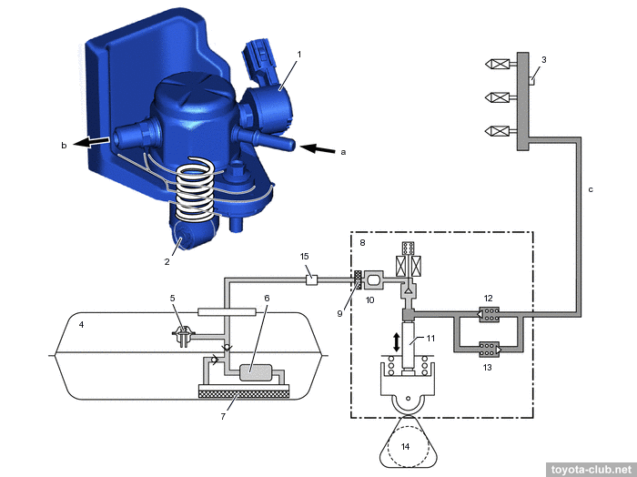
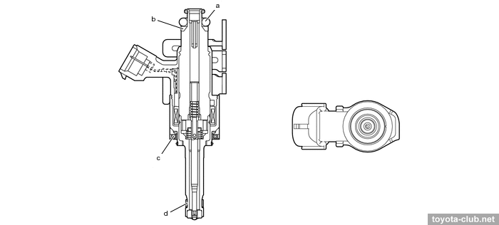
Injection pump (high pressure) - single-plunger with control valve, relief valve, check valve and pulsation damper at inlet. Installed on the bearing cap and driven by the exhaust camshaft cam. The fuel pressure is regulated in the range 4..20 MPa depending on the driving conditions.
1 - spill control valve, 2 - roller lifter, 3 - fuel pressure sensor (high pressure), 4 - fuel tank, 5 - fuel main valve, 6 - fuel pump (low pressure), 7 - fuel filter, 8 - fuel pump (high pressure), 9 - filter, 10 - fuel pressure pulsation damper, 11 - plunger, 12 - check valve, 13 - fuel relief valve, 14 - exhaust camshaft, 15 - fuel pressure sensor (low pressure). a - low-pressure fuel (from fuel tank), b - high-pressure fuel (to fuel delivery pipe), c - high-pressure fuel pipe
|
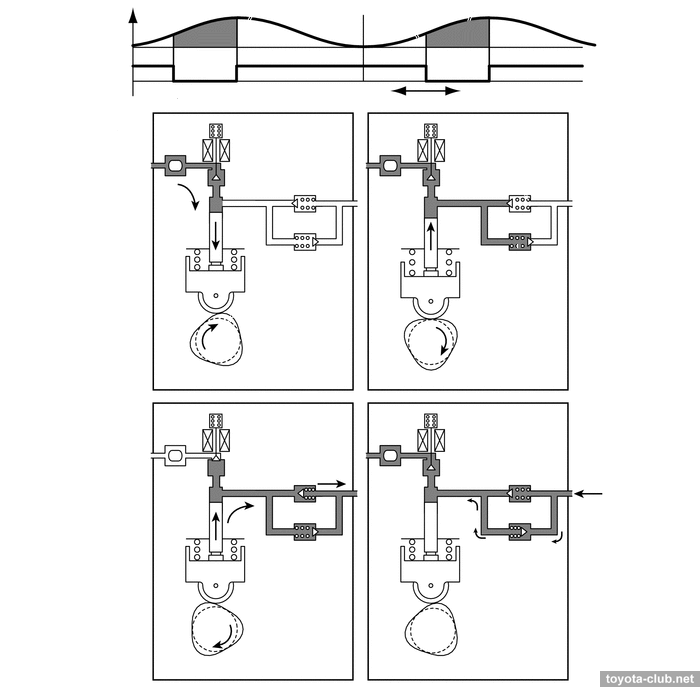
- At inlet stroke the plunger moves downward and fuel draws into the pumping chamber through open control valve.
- At the beginning of the compression stroke part of the fuel is returned while control valve is open (the specified fuel pressure is set).
- At the end of the compression stroke control valve is closed and the pressurized fuel through the check valve is supplied into the fuel rail.
- If the pressure in the manifold becomes abnormally high, a mechanical relief valve opens to dump part of the fuel back to the pump.
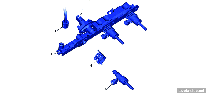
Fuel rail (high pressure) - steel-pressed, contains fuel pressure sensor to provide feedback. Injectors are held by spring holders that reduce vibration and prevent them from moving during starting (when the pressure in the cylinder is higher than the fuel pressure in the rail).
1 - high-pressure fuel pipe, 2 - fuel delivery pipe, 3 - fuel pressure sensor, 4 - nozzle holder clamp, 5 - fuel injector
|
Injectors (high pressure) - inject fuel into the cylinders as complex shape torch for maximum atomization of gasoline. PTFE seal rings further reduce nozzle noise and vibration.
a - o-ring, b - backup ring, c - insulator, d - teflon sealant
|
· Mass air flow sensor (MAF) - "slot-in" type - air flow is determined by the temperature difference of two sensing elements, between which the heater is located.
1 - intake mass air flow meter. a - upstream side, b - downstream side, c - heater, d - temperature distribution without airflow, e - flow rate detection, f - intake air
|
· Throttle valve - electronically controlled (ETCS): DC motor, dual-channel non-contact position sensor (Hall effect)
· Accelerator pedal position sensor - dual-channel non-contact (Hall effect).
· Knock sensor - flat piezoelectric type.
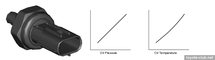
· Oil pressure / oil temperature combined sensor
· Fuel pressure sensors - for high and low pressure circuits
· Vacuum sensor.
· Crankshaft and camshaft position sensors are MRE-type.
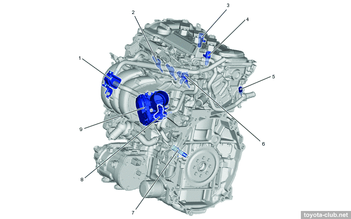
1 - canister purge VSV, 2 - fuel pressure sensor (high pressure), 3 - fuel pressure sensor (low pressure), 4 - camshaft position sensor (exhaust), 5 - camshaft position sensor (intake), 6 - inlection pump (high pressure), 7 - coolant temperature sensor, 8 - fuel injector, 9 - throttle body, 10 - crankshaft position sensor, 11 - knock sensor, 12 - water inlet with thermostat
|
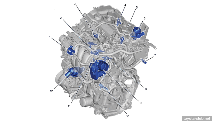
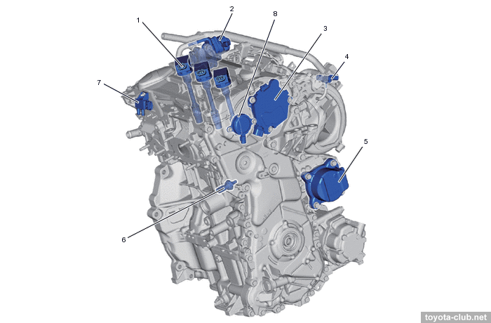
1 - ignition coil, 2 - EGR valve, 3 - VVT control solenoid (intake), 4 - vacuum sensor, 5 - water pump, 6 - oil pressure and temperature sensor, 7 - differential pressure sensor, 8 - VVT control solenoid (exhaust)
|
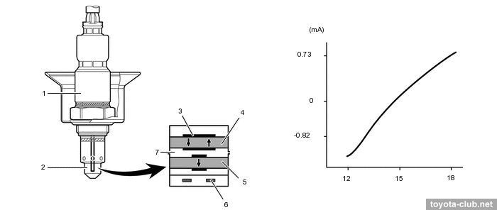
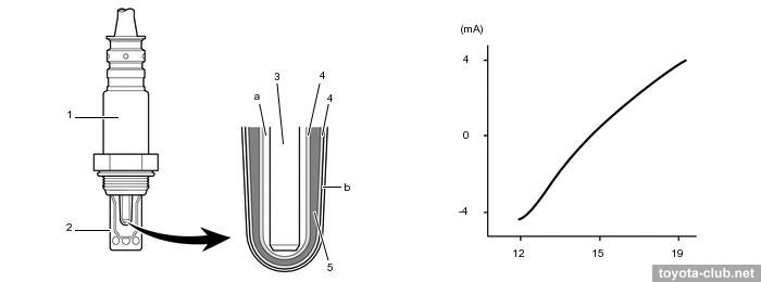
· Oxygen sensors - air-fuel ratio sensor (AFS) - planar-type upstream and cup-type downstream of catalyst (different heaters).
1 - air-fuel ratio sensor (B1S1) (planar type), 2 - cover, 3 - Pt, 4 - pumping cell (Zr), 5 - Nernst cell (Zr), 6 - heater, 7 - exhaust gas
|
1 - air-fuel ratio sensor (B1S2) (cup type), 2 - cover, 3 - heater, 4 - Pt, 5 - sensing element (Zr). a - atmosphere, b - ceramic coating
|
Ecology
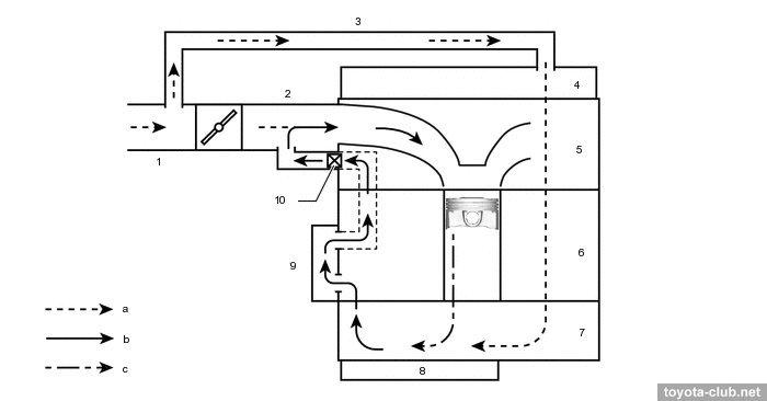
• Crankcase ventilation (PCV) - with the separator, which should make oil recovery more efficient and slow down oil aging, reduce oil burn and sludge formation. PCV valve is built-in between the cylinder head and the intake manifold to rid of the extra vacuum hose. The valve closes to reduce the bypass of crankcase gases at high vacuum in the intake manifold, and opens at low vacuum.
1 - PCV valve, 2 - intake manifold, 3 - ventilation case 1 (separator), 4 - ventilation hose 2
|
1 - air cleaner hose 1, 2 - intake manifold, 3 - ventilation hose 2, 4 - cylinder head cover, 5 - cylinder head, 6 - cylinder block, 7 - stiffening crankcase, 8 - oil pan, 9 - ventilation case 1 (separator), 10 - PCV valve. a - fresh air, b - blowby gas + fresh air, c - blowby gas
|
• Fuel evaporation system (EVAP) - a simple version, with one PWM-controlled canister purge valve.
1 - canister purge VSV, 2 - fuel tank, 3 - fuel pump module (pump/gauge/canister), 4 - ECM
|
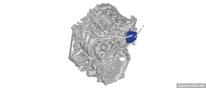
• Exhaust gas recirculation (EGR) - is the main source of carbon deposits in the intake paths and on the valves. The gases taken out downstream the catalyst pass through the channel in the cylinder head to the cooler and then to the water-cooled valve driven by a stepper motor.
1 - intake manifold, 2 - EGR pipe, 3 - EGR valve, 4 - EGR cooler. a - EGR distribution, b - cylinder head passage
|
• Particulate filter (GPF) - see details at "Toyota gasoline engines particulate filters" (GPF)".
1 - differential pressure sensor, 2 - AFS 1, 3 - ECM, 4 - AFS 2, 5 - front exhaust pipe (GPF)
|
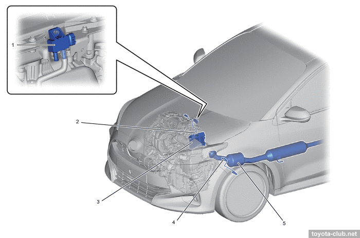
Electrical
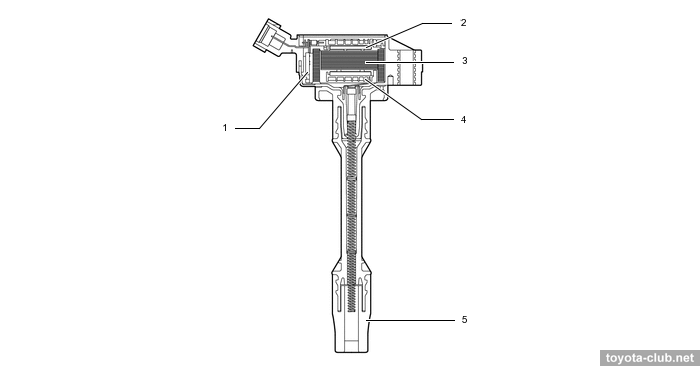
Ignition system - DIS-3 type (separate coil with integrated igniter for each cylinder).
1 - igniter, 2 - primary coil, 3 - iron core, 4 - secondary coil, 5 - plug cap
|
Spark plugs - Denso FC16HR-Q8 or NGK DILKAR6T8 - "thin" (reduced thread diameter), central electrode tip made of iridium alloy, ground electrode with platinum coating, extended threaded part (Long Reach).
Starting system system provides two options for starter (planetary gear type): for conventional models - 1.0 kW, for models with a stop-start system - 1.2 kW with a built-in ICR relay, which should stabilize the system voltage during starting.
The accessory drive is as simple as possible, with the automatic tensioner. Alternator split-pulley contains a spring to reduce the torsional vibrations.
1 - generator, 2 - tensioner, 3 - crankshaft, 4 - A/C compressor
|
If we consider -FXE as a simplified version of -FKS, then it will be enough to note the main differences.
Engine mechanical
• VVT actuators for both camshafts are installed (DVVT - Dual Variable Valve Timing). There are electrical variable valve timing mechanism for intake (VVT-iE) and traditional hydraulic for exhaust (VVT-i). Timing variations range - 70° for intake and 40° for exhaust. More about Toyota VVT operation.
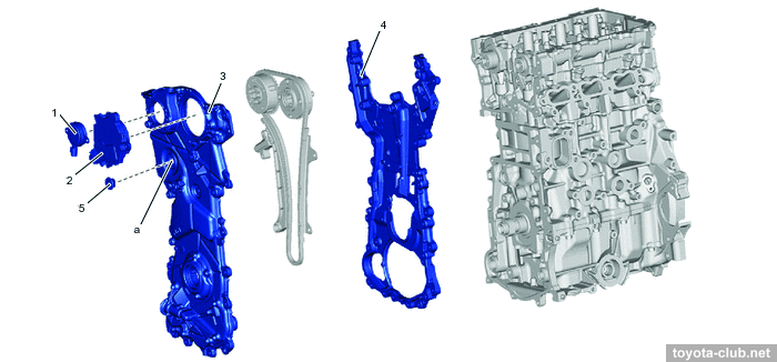
1 - VVT solenoid (exhaust), 2 - VVT-iE control motor / EDU (intake), 3 - front cover, 4 - rear cover, 5 - plug. a - service hole
|
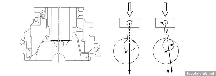
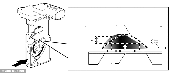
• Balancer shaft is not used - the engine operating range at hybrids allows it.
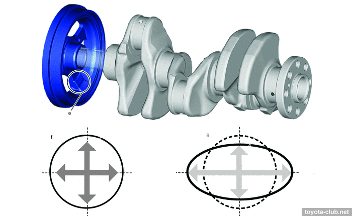
• The unbalanced weight is built into the crankshaft pulley, which reduces the vertical component of vibrations typical of a 3-cylinder engine.
a - unbalanced mass, f - conventional 3-cylinder engine vibration, g - vibration after adding unbalanced mass
|
• Coolant circuit - without transmission oil cooler.
• Officially prescribed oil viscosity:
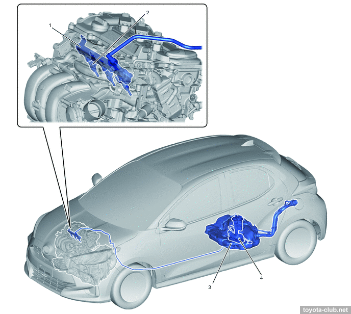
Fuel system / Engine control (EFI)
Fuel injection - multipoint (sequential, synchronous or asynchronous). Fuel system - without a return line, with the pressure regulator, and the fuel filter, and EVAP canister built in pump module.
1 - fuel delivery pipe (fuel rail), 2 - injector, 3 - tank, 4 - fuel pump module (pump, filter, canister, gauge)
|
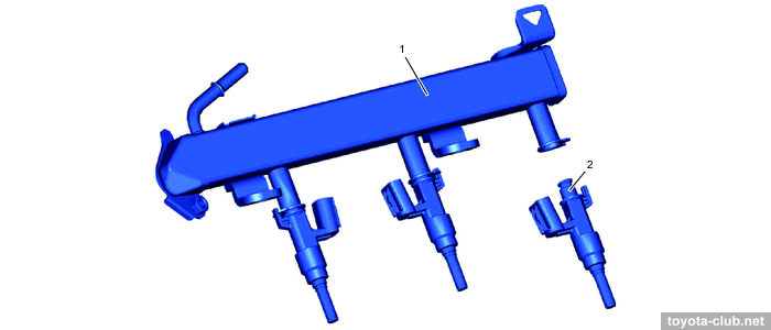
Fuel rail (low pressure) - steel-stamped; its walls themselves act as a damper for fuel pressure pulsations. The pressure sensor is installed in the rail.
1 - fuel delivery pipe (fuel rail), 2 - injector
|
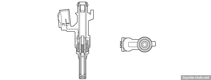
Injectors - with a long 10-point nozzle that delivers fuel into the air stream.
Components and subsystems are similar to -FKS engine (of course, with the exception of high pressure circuit elements).
1 - canister purge VSV, 2 - fuel injector, 3 - camshaft position sensor (exhaust), 4 - camshaft position sensor (intake), 5 - coolant temperature sensor, 6 - fuel pressure sensor, 7 - crankshaft position sensor, 8 - knock sensor, 9 - throttle body
|
1 - ignition coil, 2 - EGR valve, 3 - VVT-iE control motor / EDU, 4 - vacuum sensor, 5 - water pump, 6 - oil pressure and temperature sensor, 7 - differential pressure sensor, 8 - VVT-i solenoid
|
• For the first time, the particulate filter used for Toyota engine with multipoint injection (which was recently required only for D-4 engines to comply Euro-6).
The real experience of operating and repairing of the new engines is a matter of the future, so we will have just to make comments based on the results of an objective comparison of two versions with different types of engine.
+ The operation sound of both 3-cylinder engines is non-irritating. Noise comfort (from engine) is at least as good as in the previous car generation with 1NZ and much better than in the larger models with A25 engine.
- Both versions accelerate 0-100 at least a second worse than written in the specifications.
M15A-FXE
+ The hybrid version is noticeably quieter in all driving modes, including the most intensive acceleration.
+ The fuel consumption of the hybrid in real conditions is indeed one third lower than that of a purely gasoline.
+ Acceleration from standstill to city speeds the hybrid makes a little faster.
M15A-FKS
+ As the speed increases, the pure gasoline version wins back the initial lag and gradually goes into the lead.
+ Gasoline version performs faster the overtaking (acceleration 60-110 km/h).
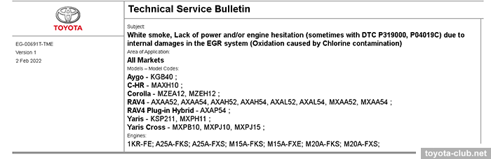
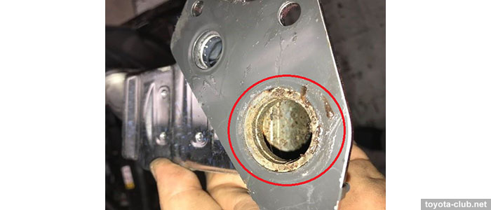
• Upd. The bad news for European car owners: Toyota has refused to treat numerous problems with the EGR cooler as a design defect and a warranty claim.
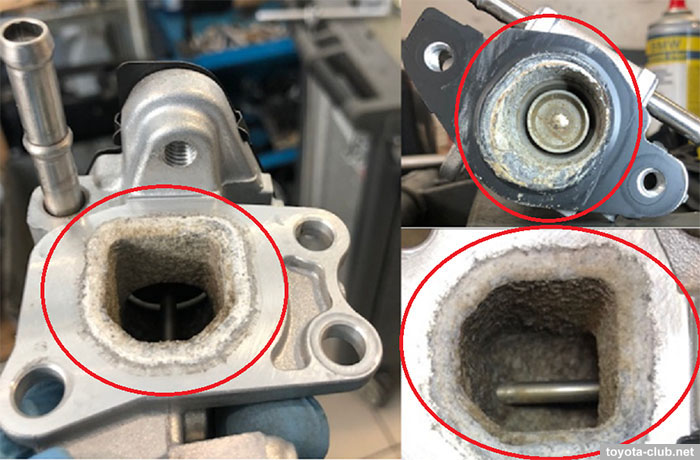
As known, due to the destruction of the EGR cooler heat exchanger, coolant ingress the EGR channels and then into the cylinders. At the same time, abundant deposits (in the form of powder or crystals) form in the gas channels, often the EGR valve sticks. External symptoms - white smoke from the exhaust pipe, engine hesitation and power loss, the appearance of DTC codes (P319000, P04019C etc.), antifreeze level drops and engine overheat is possible. All this take place on cars rather new and at rather low mileage.
In general, the reason is clear - since the new generation (Dynamic Force) Toyota began to equip all the gasoline engines with high-performance EGR systems with water cooling, but did not provide for the necessary durability and corrosion resistance for real operating conditions. EGR coolers have long been used in diesel models, and internal heat exchanger leaks also occur there, but such cases are much less resonant (besides, fatigue cracks covered by the warranty are among the reasons). Also owners of hybrid 2ZR-FXE (where EGR also plays an important role) meet a similar problem.
However, in this case, Toyota decided to consider corrosion due to using of low-quality gasoline with an admixture of chlorine compounds as the cause and set out its position in the latest TSB EG-00691T-TME (02.02.2022). Repairs should be paid by the owners (the usual bill in S.Europe was $1500 as of 2021), but regional offices can provide a discount. At the same time, the service life of the new EGR cooler is also completely unpredictable.
|
Toyota engines review
·
AZ ·
MZ ·
NZ ·
SZ ·
ZZ ·
AR ·
GR ·
KR ·
NR ·
ZR ·
AD ·
GD ·
ND ·
VD ·
A25.M20 ·
F33 ·
G16 ·
M15 ·
V35 ·
|
|
|