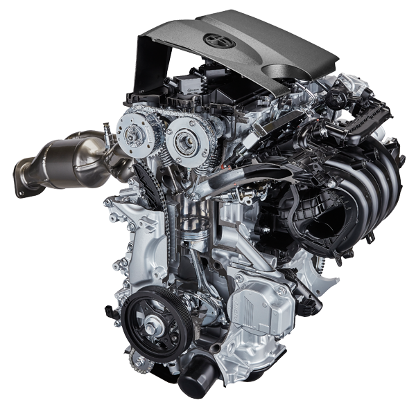
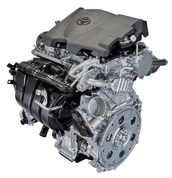
The first engine of the new series under "Dynamic Force" designation debuted in 2016 (2.5), the second - in 2017 (3.5), the third - in 2018 (2.0).
· A25A-FKS (2.5) and M20A-FKS (2.0) - basic engines of the series, D-4S combined injection, DVVT-iE variable valve timing, Miller cycle mode.
· A25A-FXS, M20A-FXS - version for hybrid powertrain
· A25A-FKB, M20A-FKB - flex-fuel (E85 ethanol fuel) version
· A25G-FKS, A25F-FXS, A25H-FXS, M20D-FKS, M20E-FKS, M20B-FXS, M20G-FXS - localized versions for China, manufactured by FAW-FTCE.
· M20C-FKS, M20F-FXS, A25C-FKS, A25D-FXS - localized versions for China, manufactured by GAC-GTE.
A25A-FKS (2.5 D-4S)
Most of the used technical solutions were once described in our reviews of previous series, so A25A can be considered as an evolutionary development of the 3-4 wave engines.
Engine mechanical - Cylinder block
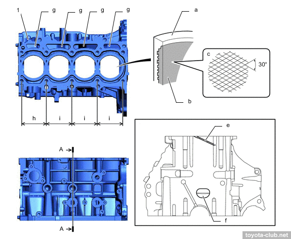
The cylinder block - open-deck type, made of aluminum (light-alloy). The cast iron liners are fused into the block material, and their special uneven outer surface provides the durable connection and improved heat sink.
The #1 cylinder has no water cooling at front side which allowed to reduce the overall length of the block. Channels for oil and antifreeze are brought together for better heat transfer - fast warming up of the cold engine and cooling under high loads. There are sloping coolant channels drilled between the cylinders.
1 - cylinder block. a - cylinder bore, b - liner, c - bore cross hatch, e - water passage, f - breather hole, g - oil drain, h - 94 mm, i - 97 mm.
There is the spacer in the water jacket installed, it allows more intensive coolant circulation near the top of the cylinder, which improves heat dissipation and helps to more evenly thermally load.
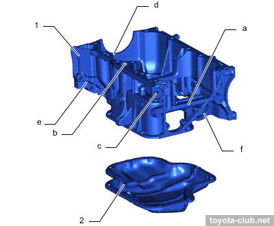
A massive alloy crankcase (or upper oil pan) is attached to the block.
1 - crankcase, 2 - oil pan. a - oil passage, b - oil drain passage, c - oil pressure control valve hole, d - rear oil seal retainer, e - rear end plate, f - oil filter bracket.
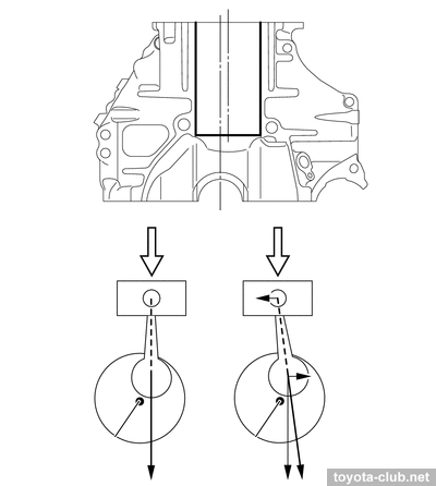
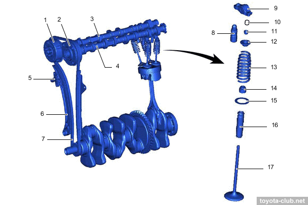
The crankshaft is installed with a 10 mm offset (the axes of the cylinders do not intersect with the longitudinal axis of the crankshaft), thus reducing the lateral component of the force exerted by the piston to the cylinder wall, reducing wear.
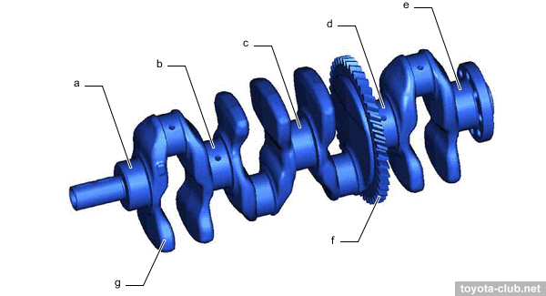
The crankshaft has 8 counterweights, narrow journals and traditional (separated) main bearing caps. The bearings have a polymer coating. The upper heads of the connecting rods are cut to reduce weight.
a-e - main bearing journal, f - balance shaft drive gear, g - balance weight.
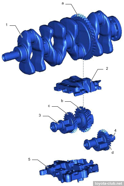
The separate balancer mechanism is driven by crankshaft via train with polymer gears. The balance shafts module is attached through the crankcase directly to the cylinder block with long bolts.
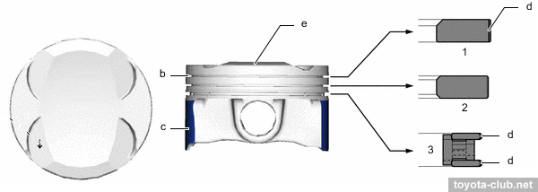
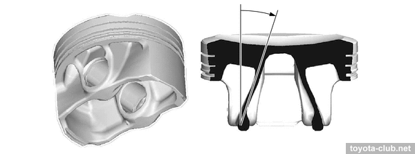
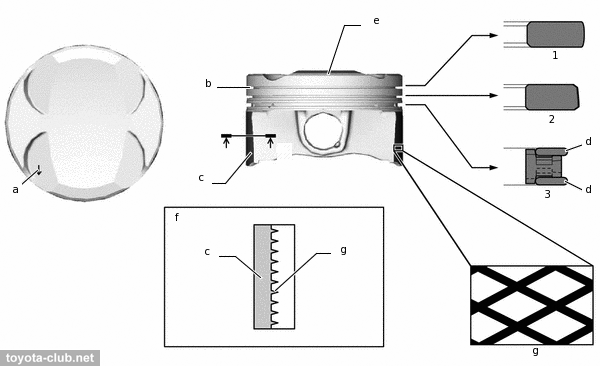
The pistons made of light-alloy, T-shaped, lightweight. The groove of the upper compression ring has an alumite coating, the edges of the upper compression and oil rings has anti-wear carbon coating (DLC - "diamond like"). The working part of the skirt is covered with a polymer coating. Pistons are connected to the connecting rods by fully floating pins and locking rings.
1 - compression ring 1, 2 - compression ring 2, 3 - oil ring. b - alumite coating, c - resin coating, d - DLC coating, e - combustion bowl.
The "walls" of the piston are noticeable sloped, which should better distribute the load to the piston pin at the expansion stroke.
The engine is highly "long-stroke" - so the piston speed shows the new absolute record for Toyota (of course, it does not extend the engine durability).
Similarly other modern Toyota engines, A25A has a high geometric compression ratio (13-14). Although it would be more accurate to say "expansion ratio" - the actual compression ratio for Miller cycle is much lower, so the engines are designed for low octane gasoline (RON 91 / Regular). Engine mechanical - Cylinder head
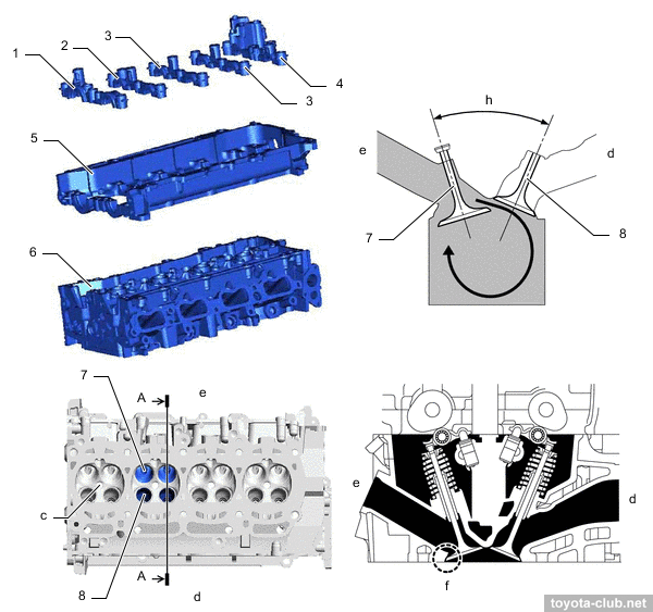
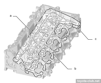
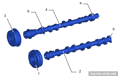
The camshafts are installed in a separate housing, which mounted on the cylinder head - it simplifies the design and manufacturing technology of cylinder head, but creates an extra joint with oil channels to be sealed.
1-4 - camshaft bearing cap, 5 - camshaft housing, 6 - cylinder head, 7 - intake valve, 8 - exhaust valve. c - spark plug hole, d - exhaust side, e - intake side, f - valve seat, g - tumble flow.
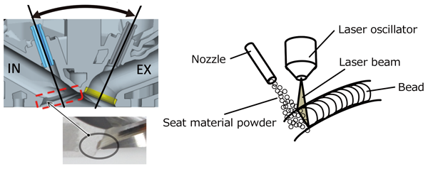
Instead of traditional (pressed) for the inlet valves special "laser-clad" seats are used (like old 1ZZ-FE). Such seat is much thinner than usual, that provides better cooling of the valves and allows to optimize the shape and size of the intake port.
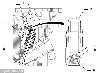
There are hydraulic lash adjusters and roller rockers in the valve mechanism.
1 - cam, 2 - valve rocker arm, 3 - valve lash adjuster. a - oil passage, b - plunger, c - check ball, d - check ball spring, e - plunger spring.
The cooling jacket of the head is divided into two levels to accelerate the flow of antifreeze.
a - upper water jacket, b - lower water jacket, c - sub-jacket.
Size optimization of the exhaust ports should help the exhaust gases cooling. The EGR channel passes directly through the head.
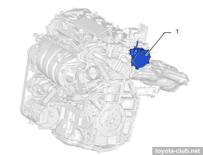
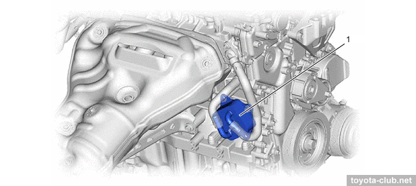
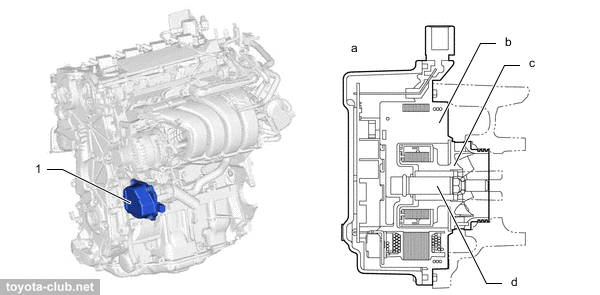
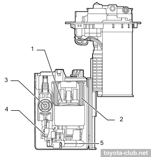
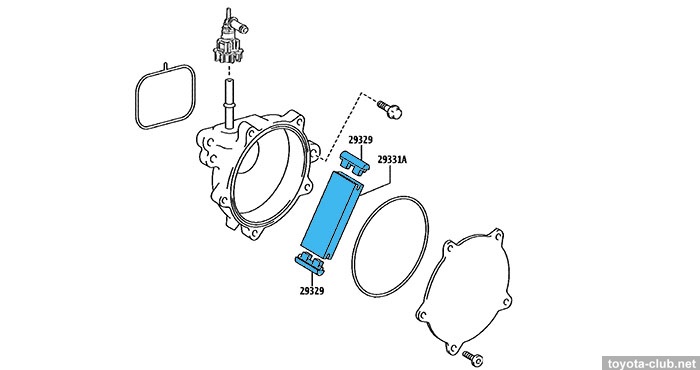
A vacuum pump is required because of D-4 engine does not provide enough vacuum in the intake manifold for brake booster operation. However, as for ZR engines, the pump design will cause the same problems in the future.
1 - vacuum pump
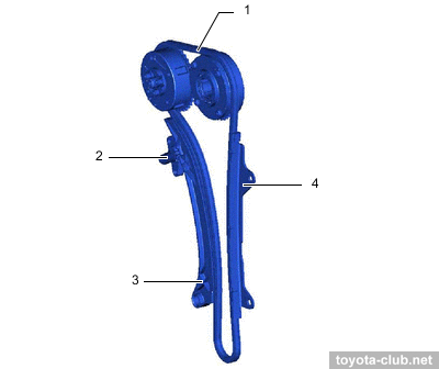
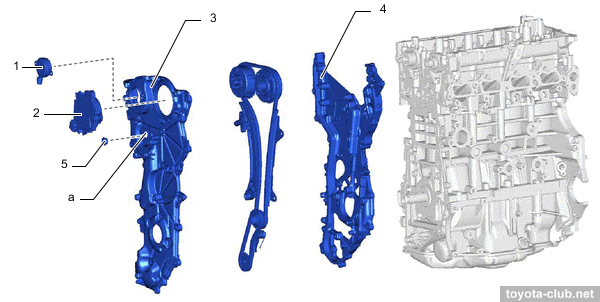
The timing chain is closed with two alloy covers (VVT-iE controller and the VVT-i valve are attached to the front cover).
1 - cam timing oil control solenoid, 2 - cam timing control motor, 3 - timing gear cover, 4 - timing chain cover, 5 - straight screw plug. a - service hole.
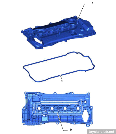
The cylinder head of the block is covered with alloy cover, provided with oil delivery pipe for the rockers lubrication.
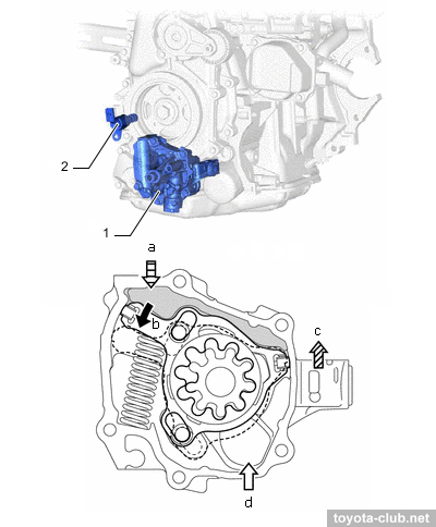
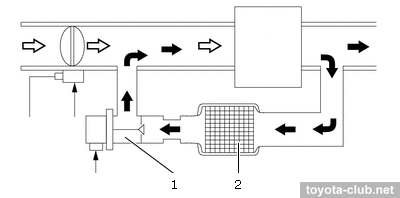
The main innovation is a variable-discharge oil pump - the second generation, with the principle of operation different from AR and ZR series.
Trochoidal pump is driven via an additional short chain. The ECM controls the pump operation by oil pressure control valve, depending on the engine temperature, speed and other parameters.
Under the action of pressure in the control chamber, a regulator moves and changes the mutual position of the internal and external rotors, thereby achieving a smooth change of the oil charge volume.
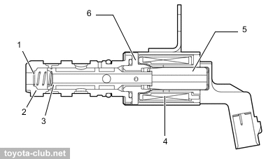
1 - oil pump, 2 - oil pressure control valve. a - from oil pressure control valve, b - movement of oil pump regulator, c - to oil system, d - from oil strainer
1 - regulator, 2 - control chamber, 3 - rotor
The oil filter is installed horizontally at the engine front.It is a normal spin-on type filter, unlike the popular on previous engine generation but absolutely vicious "economical" replaceable paper cartridges.
1 - oil filter
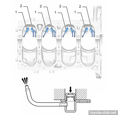
Oil nozzles that lubricate and cool the pistons are provided (two oil nozzles for each, one of them with double sprayer). The oil to nozzles comes through check valves and built-in filters.
1 - oil nozzle, 2 - oil nozzle 2. b - filter
The oil level sensor is installed under the balancer module.
1 - oil level sensor
Optionally, a water oil cooler may be installed.
1 - oil cooler
Cooling system
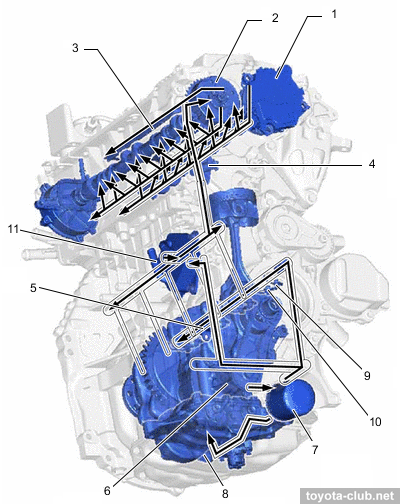
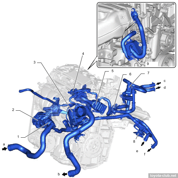
1 - water inlet with thermostat, 2 - water pump, 3 - throttle body, 4 - EGR valve, 5 - EGR cooler, 6 - water by-pass outlet, 7 - flow shutting valve (heater), 8 - flow shutting valve (ATF), 9 - oil cooler. a - from radiator, b - to radiator, c - from heater, d - to heater, e - from transmission oil cooler, f - to transmission oil cooler.
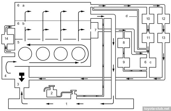
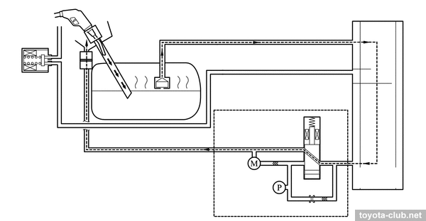
A fundamentally new cooling system for Toyota - with an electric pump, electric thermostat and shut-off valves.
1 - radiator, 2 - reserve tank, 3 - water inlet with thermostat, 4 - water pump, 5 - cylinder block, 6 - cylinder head, 7 - EGR cooler, 8 - EGR valve, 9 - throttle body, 10 - flow shutting valve (heater), 11 - heater radiator, 12 - transmission oil cooler, 13 - flow shutting valve (ATF), 14 - oil cooler. a - upper water jacket, b - lower water jacket, c - sub-jacket, d - passage
The electric pump allows you to adjust the coolant flow at the discretion of ECM.
1 - water pump. b - stator, c - rotor, d - shaft
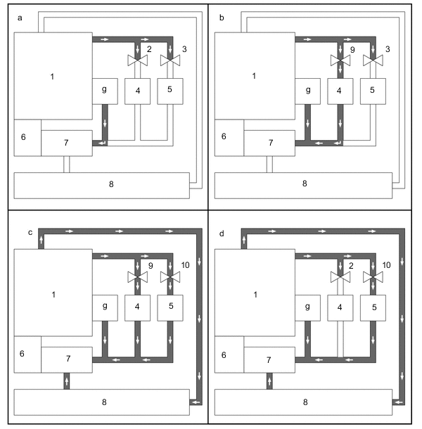
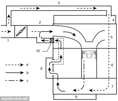
The accelerated warm-up function provides the fastest reaching of economical operation modes and is performed by two shut-off valves that can exclude the heater and the transmission oil cooler from the circulation.
1 - engine, 2 - flow shutting valve (heater) (closed), 3 - flow shutting valve (ATF) (closed), 4 - heater radiator, 5 - transmission oil cooler, 6 - water pump, 7 - water inlet with thermostat, 8 - radiator, 9 - flow shutting valve (heater) (open), 10 - flow shutting valve (ATF) (open). a - early warm-up, b - heater priority, c - output enhancement, d - max cool, e - when current is not applied to the thermostat with heater, coolant flow volume is increased, thus output is enhanced. additionally, applying current to the thermostat with heater decreases thermostat opening temperature, ensuring cooler efficiency, f - this discontinues coolant flow of the heater radiator unit sub-assembly, ensuring cooler efficiency, g - EGR cooler.
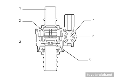
When the current is applied, the valve is held in the closed position. If the current is not applied and the pump is running, the valve opens under the force of the coolant flow and remains open until the flow stops.
The nominal temperature of the thermostat opening is 80-84°C - so the new engines in Toyota's best traditions remained "cold", keeping this great advantage over the "hot" engines of the European makers.
The current supply to the thermostat heater allows to increase its opening under significant load conditions, lowering the temperature in advance and providing higher power output without the risk of detonation.
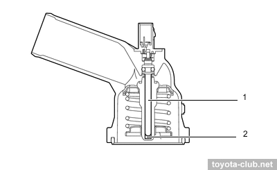
1 - heater, 2 - wax
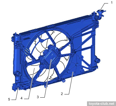
The engines are equipped with separate fan motor control unit, which allows to adjust fan speed depending on the coolant temperature, refrigerant pressure, vehicle speed and engine speed. The fan - single, large diameter.
1 - radiator cap, 2 - fan shroud, 3 - cooling fan motor, 4 - fan, 5 - drain plug
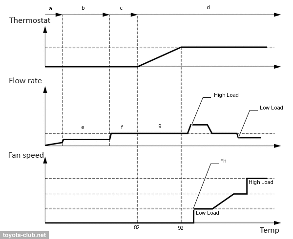
Integrated control of the thermostat, water pump, valves and fan motor provides improved warm-up, reduced friction losses and better fuel economy.
a - no circulation (starting calibration), b - restricted flow rate, c - normal flow rate, d - combustion chamber wall temperature control, e - flow rate for minimum piston slap, f - flow rate (10° temperature difference between engine inlet and outlet), g - normal flow rate (after thermostat open depending on the load), h - cooling fan ON temperature varies (depending on the driving conditions)
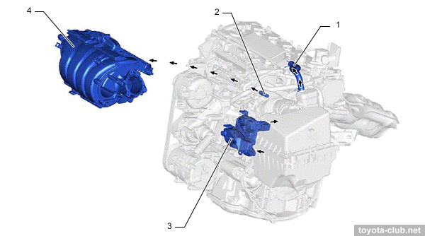
Intake and exhaust
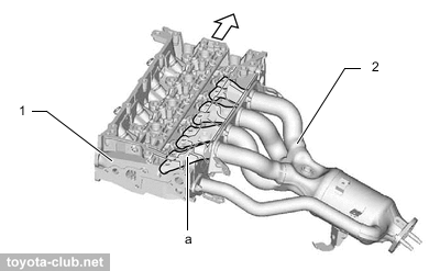
Previously the location of the intake and exhaust manifold of Toyota engines did not have an unambiguous logic, but DF concept specially stipulates exhaust at the bulkhead side.
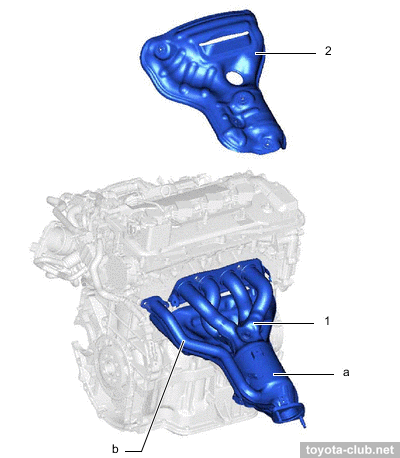
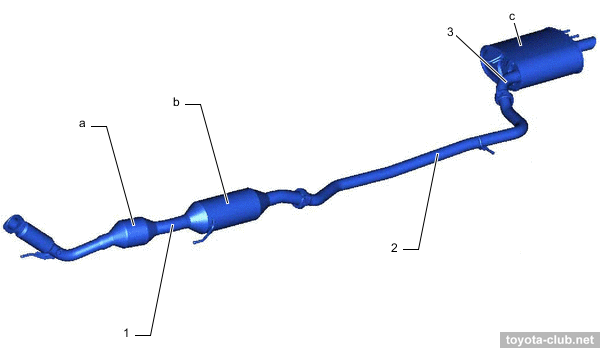
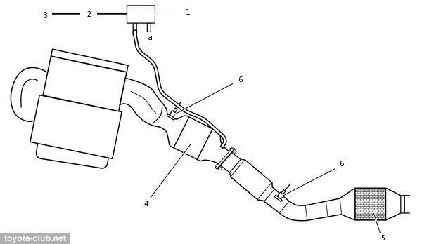
A25A has traditional steel exhaust manifold with a built-in catalyst, equal length pipes and an EGR pipe. Downstream the second catalyst, pre- and main mufflers are located.
1 - exhaust manifold, 2 - heat insulator. a - TWC, b - EGR gas passage
1 - front exhaust pipe, 2 - center exhaust pipe, 3 - tail exhaust pipe. a - TWC, b - sub muffler, c - main muffler.
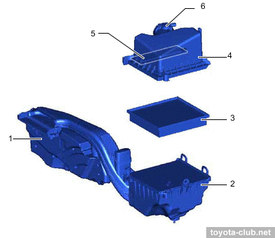
The intake is extremely simple, without any geometry change devices, with a traditional electronic throttle control (ETCS-i). A paper air filter with a microfibre layer can be supplemented with a carbon filter to trap hydrocarbon particles from the intake duct during parking. The inlet airpipe is equipped with a large resonator.
1 - inlet, 2 - air cleaner case, 3 - filter element, 4 - cap, 5 - carbon filter, 6 - mass air flow meter
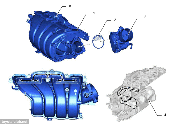
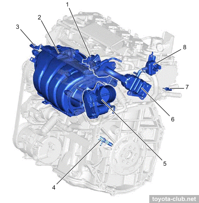
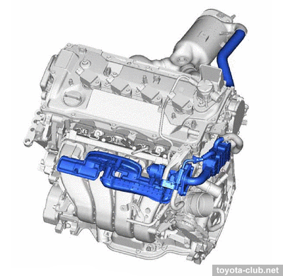
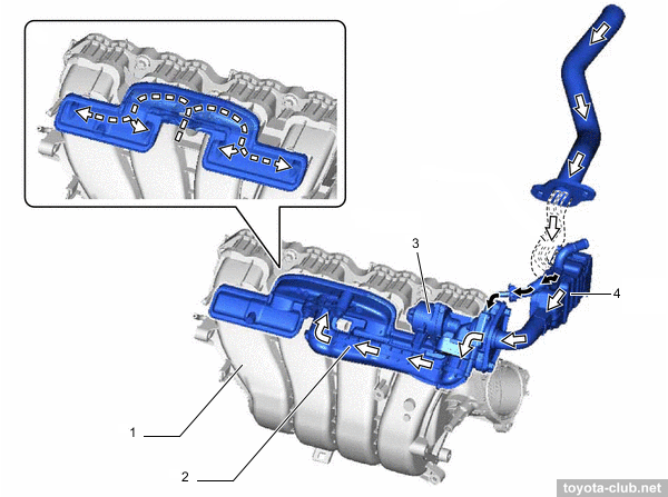
EGR collector is integrated in the plastic intake manifold and distributes the exhaust gases evenly among the cylinders.
1 - intake manifold, 2 - gasket, 3 - throttle body, 4 - insulator. a - EGR delivery, b - EGR gas flow, c - blowby gas flow.
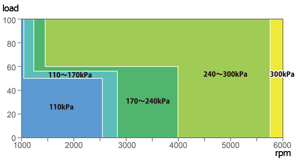
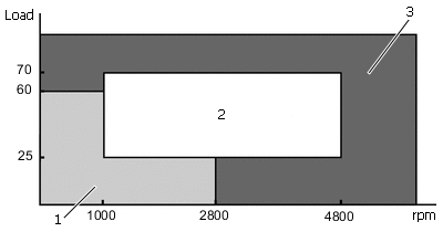
Fuel injection - combined: directly in the combustion chamber and multipoint in the inlet ports. At low to medium loads - combined injection is applied - homogeneous mixture increases the stability of the combustion process and reduces emissions. Under a heavy load use direct fuel injection - the evaporation of the fuel in the cylinder filling mass improves and reduces the tendency to knock.
1 - injection in port, 2 - injection in cylinder + port, 3 - injection in cylinder.
- Stratified combustion mode. Fuel is supplied in the intake ports on the exhaust stroke. On the intake stroke after the opening of the valves in the cylinder receives a homogeneous lean mixture. At the end of the compression stroke, additional fuel is injected directly into the cylinder, allowing to enrich the mixture near the spark plug. This facilitates the initial ignition, is then distributed on the all lean mixture charge in the remaining volume of the combustion chamber. This mode is applied after a cold start to retard ignition timing and to increase the exhaust gas temperature for accelerate catalyst warming up.
- Homogenous mixture mode. Fuel is supplied in the intake ports on the expansion, exhaust and intake strokes. At the beginning of the intake stroke, additional fuel is injected directly into the cylinder and evenly mixed with the incoming charge. Homogeneous air-fuel mixture is compressed and then ignited. Due to the evaporation of injected fuel, air charge in the cylinder is cooled improves cylinder filling.
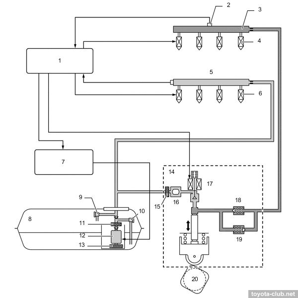
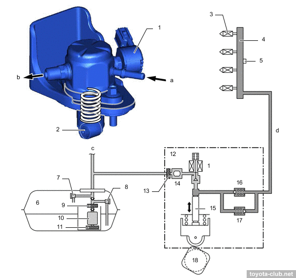
Fuel pump (LP) delivers fuel from the tank at a pressure of 300-530 kPa to the injection pump and to LP injectors. The pump is controlled by ECM via a separate control unit. The pump control unit with PWM provides stepless adjustment of the pump speed, providing the required amount of supply. An additional function is to turn off the pump when any of the airbags are activated.
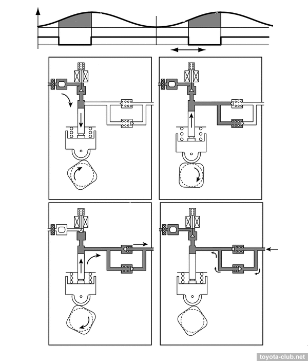
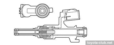
Injection pump (HP) - single-plunger with control valve, relief valve, check valve and pulsation damper at inlet. Mounted on the valve cover and driven by 4-lobes cam of the camshaft. The fuel pressure is regulated in the range 2.4..20 MPa depending on the driving conditions.
- At inlet stroke the plunger moves downward and fuel draws into the pumping chamber.
- At the beginning of the compression stroke part of the fuel is returned while control valve is open (the specified fuel pressure is set).
- At the end of the compression stroke control valve is closed and the pressurized fuel through the check valve is supplied into the fuel rail.
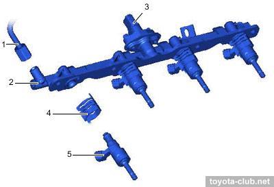
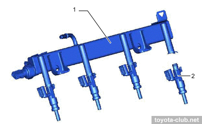
Fuel rail (HP) - steel stamped, a pressure sensor provides feedback to ECU. The injectors are held by spring holders that reduce vibration and do not allow them to move during start-up (when the pressure in the cylinder is higher than the fuel pressure in the rail).
Fuel rail (LP) - steel stamped, its walls themselves serve as fuel pressure pulsation damper. The pressure sensor is installed in the rail.
1 - fuel delivery pipe with sensor (low pressure), 2 - port fuel injector
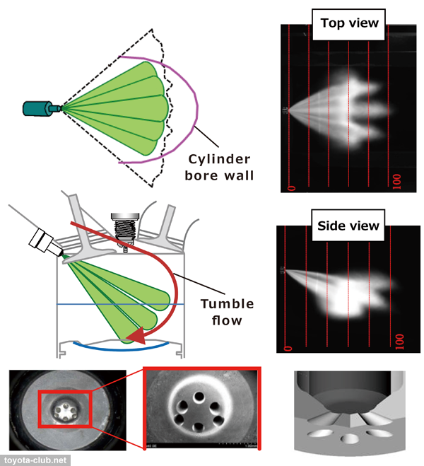
Injectors (HP) - with a 6-point sprayer, inject fuel into cylinders as complex shaped torch for maximum atomization of gasoline. Sealing teflon (PTFE) rings further reduce vibration.
Injectors (LP) - with a long 10-point sprayer that delivers fuel into the air stream and minimizes fuel impact to the walls.
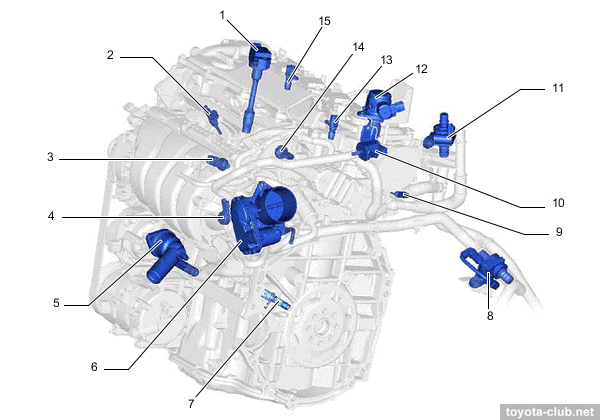
Control system
The set of electronic components of A25A not much differs from previous engines.
- Mass air flow sensor (MAF) - "hot wire" type, combined with the intake temperature sensor.
- Throttle - fully electronically controlled (ETCS): DC motor, dual-channel non-contact position sensor (Hall effect).
- Accelerator pedal position sensor - dual-channel non-contact (Hall effect).
- Knock sensors - "flat" wideband piezoelectric.
- Oil pressure sensor - really "sensor", not a simple two-position switch.
- Fuel pressure sensors - for high and low pressure circuits.
- Vacuum sensor.
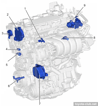
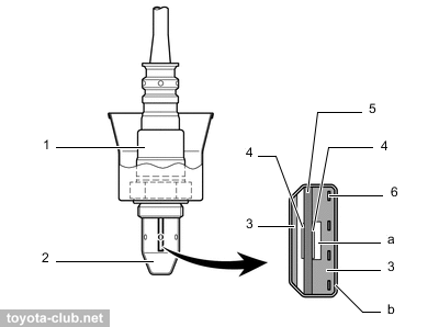
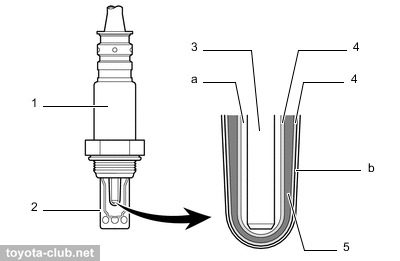
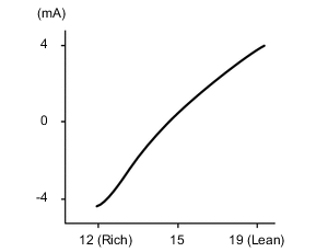
Oxygen sensors - both air-fuel ratio sensor (AFS, 89467-) - planar upstream and cup-type downstream (different heater type).
1 - air fuel ratio sensor (planar), 2 - cover, 3 - alumina, 4 - platinum electrode, 5 - sensor (zirconia), 6 - heater. a - atmosphere, b - coating (ceramic)
1 - air fuel ratio sensor (cup), 2 - cover, 3 - heater, 4 - platinum electrode, 5 - sensor (zirconia). a - atmosphere, b - coating (ceramic)
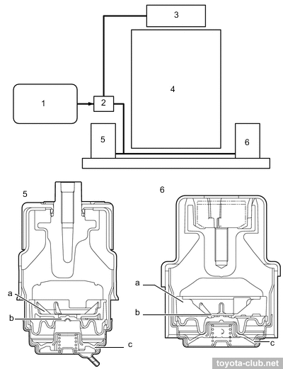
Active mounts - are used to reduce engine vibrations. ECM regulates vacuum supply to them by VSV. When VSV is ON - no vacuum applied to the mounts, the diaphragm is closed, the fluid moves through the free channels. When VSV is OFF - the vacuum is applied to the mounts, the diaphragm opens, the fluid moves through the blocked channels.
1 - ECM, 2 - VSV, 3 - vacuum pump, 4 - engine, 5 - front engine mounting insulator, 6 - rear engine mounting insulator. a - idle orifice, b - lock-up orifice, c - diaphragm.
Ecology
• PCV (crankcase ventilation) - with a special separator, which should make oil separation more efficient and reduce the oil deterioration. PCV valve is built-in between the cylinder head and the intake manifold to rid of the extra vacuum hose.
1 - air cleaner hose 1, 2 - intake manifold, 3 - ventilation hose 2, 4 - cylinder head cover, 5 - cylinder head, 6 - cylinder block, 7 - crankcase, 8 - oil pan, 9 - ventilation case 1, 10 - PCV valve. a - fresh air, b - blowby gas + fresh air, c - blowby gas.
• EGR (exhaust gas recirculation) - inevitable evil, which serves (in theory) to lower the combustion temperature and to reduce the nitrogen oxides in the exhaust gas, but in practice it provides only common problems with carbon deposits in the intake paths and on the valves. Soon let's see whether it is possible to shut off it without consequences (at least, there is no feedback by EGR temperature sensor here).
1 - EGR valve, 2 - EGR cooler
The gases taken out downstream the catalyst pass through the channel in the cylinder head to the cooler and then to the valve. The EGR valve (also water-cooled) is driven by a stepper motor.
Then the gases flow to the EGR manifold, which evenly delivers gases into each cylinder.
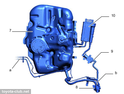
• EVAP (fuel evaporation) system - rather complicated, the similar one previously used only for North American market. It can be attributed as 6th generation of Toyota EVAP - with ORVR function, a vapor pressure sensor, a leakage control pump and other unnecessary elements.
7 - fuel tank, 8 - canister filter, 9 - canister pump module (vent valve, leak detection pump, canister pressure sensor), 10 - canister. a - purge air line, b - fresh air line
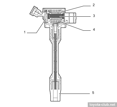
Ignition system
DIS-4 type (separate ignition coil with built-in igniter for each cylinder). The basic ignition timing is -4° to 40° BTDC, at starting is fixed at 5° BTDC.
1 - igniter, 2 - primary coil, 3 - iron core, 4 - secondary coil, 5 - plug cap
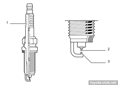
Spark plugs - Denso FC16HR-Q8 - "thin" (reduced thread diameter), central electrode tip made of iridium alloy, ground electrode with platinum coating, extended threaded part (Long Reach).
1 - insulator, 2 - iridium tip, 3 - platinum tip
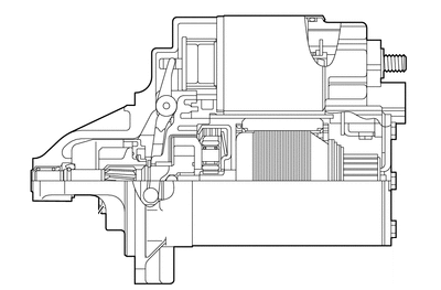
Starting system
1.3 kW starter with a planetary gear is used.
Charging system
100 A (1200 W) alternator with segment coil is used.
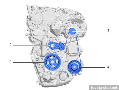
The electric water pump was applied, so the accessories drive is very simplified. The belt adjusting - by automatic tensioner. Alternator split-pulley contains a spring to to reduce the torsional vibrations.
We could replace just a few illustrations in the text above, add one paragraph and call it "a new article on M20A engines". But it is more correct to repeat that 2.0 engines are structurally identical to 2.5 ones and enough to list a few differences.
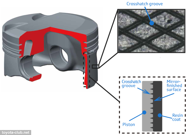
• Laser notch on the piston skirts, which should enhance oil retention.
1 - upper compression ring, 2 - lower compression ring, 3 - oil ring. a - front mark, b - alumite coating, c - polymer coating, d - carbon coating (DLC), g - crosshatch
• Slightly "cold" spark plugs (FC20HR-Q8)
• Nominal timing adjustment range (exhaust) about 41°
• Variety of starters (with stop-start function): 1.2 / 1.7 kW
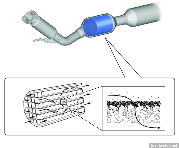
• Particulate filter (GPF)
In the 2010s, environmental standards for gasoline engines with direct injection for the first time was replenished with restrictions on emissions of particulate matter. It did not affect versions up to Euro 6, but the modification declared for compliance with Euro 6d was equipped with particulate filter (GPF) (well known from diesel engines as DPF).
1 - differential pressure sensor, 2 - ECM, 3 - combination meter, 4 - catalyst, 5 - GPF, 6 - air fuel ratio sensor, a - atmosphere
GPF is integrated in the front exhaust pipe as a ceramic structure of channels that are closed on one side or the other. When gases pass through the porous walls of the channels, solid particles and ash are deposited on their surface. GPF regeneration can be called passive - when the driving conditions allow to warm-up the filter sufficiently, the fuel cut off is activated, a clean air goes through the cylinders to exhaust pipe and the oxygen oxidizes accumulated soot particles.
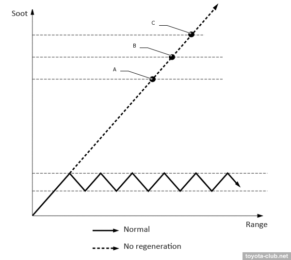
The condition of the filter is monitored using a differential pressure sensor (between the atmosphere and the exhaust upstream GPF). If for a long time the driving conditions do not allow to warm-up the filter and to start regeneration, then the accumulation of soot becomes excessive. Upon reaching certain thresholds for filter clogging, the control system will display a message inviting to service workshop, then turn on the malfunction indicator light, and finally begin to restrict engine output.
A - "Exhaust Filter Full Visit Your Dealer" message, possible power restriction; B - "Exhaust Filter Full Visit Your Dealer" message, warning light ON, possible power restriction; C - "Exhaust Filter Full Visit Your Dealer" message, warning light ON, mandatory power restriction
Experience
The history of A25 engines began in mid-2017, history of M20 - in the end of 2018. So, judging by the experience of past years, it is need to wait a rather long time for certain and statistically significant results, in the meantime monitoring DF problems in various parts of the world.
• [1] The first defect recognized by the manufacturer: an incident with oversized A25 pistons that once was supplied to the TMMK conveyor (Toyota recall J1M / J0M, NHTSA 18V200000).
• [2] The second case is also related to the North American market - total recall of cars with A25, produced in sep-dec 2019, due to a "possible" defectous cylinder block casting (Toyota recall 20TA04, NHTSA 20V064).
But let’s remind again... The renowned reliability of Toyota engines is built entirely on simple solutions, archaic designs and proven technologies. Deviation from these rules in most cases leads to sad results. A25 is perceived as the successor to the very successful 2AR-FE, but, evaluating the combination of new solutions and and "improvements", it can be guaranteed - the new motor will certainly not be as reliable and trouble-free.
So far, the main trouble of the DF engines - quite unexpectedly - it is their excessive noise. Causing discomfort at medium rpms, at the high it destroys the driver’s patience (especially unpleasant voice of A25). For hybrids, the problem is not so significant, since their internal combustion engine less time runs at high rpms, but traditional automatic transmissions and CVTs do not miss the opportunity to hold the tachometer needle at the top of the scale. This flaw seems small, but in real it may be the last decisive argument against the choice of Toyota car.
• [3] For some A25A-FKS engines manufactured before 2018/02, recall campaign 21SMD-088 (17.11.2021) has been announced - replacement of the vacuum pump vane and vane caps (29331-25010, 29329-25011).
• [4] The official regulator published a notice (10.12.2021) on a recall campaign for almost a million cars of Chinese domestic market produced in 2017-2020 (RAV4/Wildlander, C-HR, Camry, Izoa, Avalon, UX, ES). The declared problem is a corrosion of the EGR valve (supposedly caused by high chlorine content in the fuel), which can lead to its sticking and engine unstable operation, thereby affecting road safety. Prescription - replacement of at least the EGR valve with a modified one (a composite valve body instead of an all-aluminum).
• [5] The bad news for European car owners: Toyota has refused to treat numerous problems with the EGR cooler as a design defect and a warranty claim.
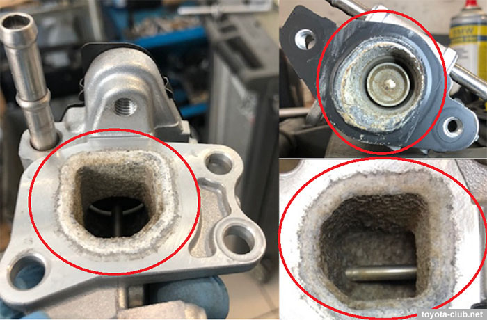
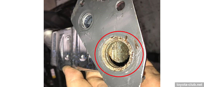
As known, due to the destruction of the EGR cooler heat exchanger, coolant ingress the EGR channels and then into the cylinders. At the same time, abundant deposits (in the form of powder or crystals) form in the gas channels, often the EGR valve sticks. External symptoms - white smoke from the exhaust pipe, engine hesitation and power loss, the appearance of DTC codes (P319000, P04019C etc.), antifreeze level drops and engine overheat is possible. All this take place on cars rather new and at rather low mileage.
In general, the reason is clear - since the new generation (Dynamic Force) Toyota began to equip all the gasoline engines with high-performance EGR systems with water cooling, but did not provide for the necessary durability and corrosion resistance for real operating conditions. EGR coolers have long been used in diesel models, and internal heat exchanger leaks also occur there, but such cases are much less resonant (besides, fatigue cracks covered by the warranty are among the reasons).
However, in this case, Toyota decided to consider corrosion due to using of low-quality gasoline with an admixture of chlorine compounds as the cause and set out its position in the latest TSB EG-00691T-TME (02.02.2022). Repairs should be paid by the owners (the usual bill in S.Europe was $1500 as of 2021), but regional offices can provide a discount. At the same time, the service life of the new EGR cooler is also completely unpredictable.
• [6] An interesting feature of the A25 and M20 engines was revealed in the American market (not a warranty case, described in T-SB-0104-21 of 17.12.2021).
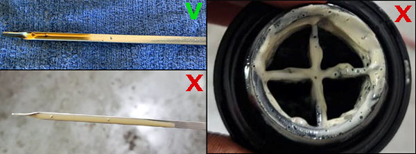
Problem: engine oil emulsion (milky/discolored), 'Oil Pressure Low' message and DTCs P05202A and P052477 may appear. Cause: during short trips at freezing temperatures, abundant condensation of moisture from blow-by gases occurs, which under such conditions is not removed naturally (evaporation after warming-up to normal operating temperatures).
Prescription: ensure the emulsion did not appear as a result of coolant leak; check for DTC during warming-up to 50°C; replacement of engine oil and filter; remove all traces of emulsion residue.
Later, a corresponding TSB for the European market appeared - EG-00731T-TME (11.04.2022).
• [7] M20 engine oil level sensor malfunction (described in EG-00852T-TME of 09.11.2022).
• [8] Fuel odor from the high-pressure fuel pump (described in T-SB-0008-23 of 26.01.2023 and customer support program 23TE01).
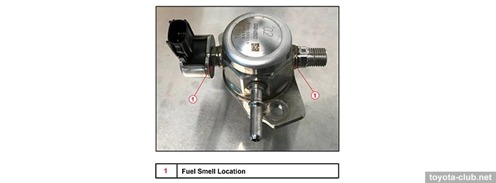
Problem: fuel odor from engine bay due to seepage from the high pressure fuel pump because of corrosion (A25A engine - Highlander, RAV4, RAV4 HV, RAV4 Prime, Venza, Sienna). Prescription: fuel pump replacement.