|
Eugenio,77
mail@toyota-club.net
© Toyota-Club.Net
Jan 2013 - Jun 2021
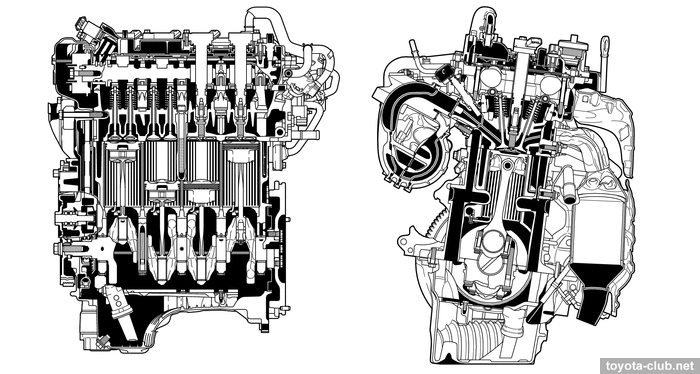
1NR-FE ·
2NR-FKE ·
8NR-FTS ·
Experience
The priority in the creation and production of new small-displacement series belonged to Daihatsu department, but NR are most known as engines of Toyota models.
First engine of the series - 1NR-FE - introduced in 2008 for European market. It immediately replaced outdated 4ZZ-FE and then gradually supplanted 2NZ-FE and 2SZ-FE from Japanese market.
In 2010-11, simplified 2NR and 3NR for emergency markets appeared. In 2014-15, -FKE versions were introduced, working by Miller cycle (1.5 partially replaced 1NZ-FE). Since 2015, the turbocharged 8NR-FTS has been produced.
| Engine |
Displacement, cm3 |
Bore x Stroke, mm |
Compression ratio |
Output, PS |
Torque, Nm |
RON |
Sys |
Market |
| 1NR-FE | 1329 | 72.5 x 80.5 | 11.5 | 99 / 6000 | 132 / 3800 | 95 | EFI | EEC |
| 1NR-FE | 1329 | 72.5 x 80.5 | 11.5 | 95 / 6000 | 119 / 4000 | 91 | EFI | JIS |
| 1NR-FBE | 1329 | 72.5 x 80.5 | - | 88-98 / 5600 | 123-128 / 4000 | 91 | EFI | Bra |
| 1NR-FKE | 1329 | 72.5 x 80.5 | 13.5 | 99 / 6000 | 121 / 4400 | 91 | EFI | JIS |
| 1NR-VE | 1329 | 72.5 x 80.5 | - | 95 / 6000 | 120 / 4200 | - | EFI | - |
| 2NR-FE | 1496 | 72.5 x 90.6 | 10.5 | 90 / 5600 | 132 / 3000 | - | EFI | Ind |
| 2NR-VE | 1496 | 72.5 x 90.6 | - | 104 / 6000 | 139 / 4200 | - | EFI | - |
| 2NR-FBE | 1496 | 72.5 x 90.6 | - | 102-107 / 5600 | 140-144 / 4000 | 91 | EFI | Bra |
| 2NR-FKE | 1496 | 72.5 x 90.6 | 13.5 | 109 / 6000 | 136 / 4400 | 91 | EFI | JIS |
| 3NR-FE | 1197 | 72.5 x 72.5 | 10.5 | 80 / 5600 | 104 / 3100 | - | EFI | Ind |
| 3NR-FE | 1197 | 72.5 x 72.5 | 11.5 | 86 / 6000 | 108 / 4000 | - | EFI | - |
| 4NR-FE | 1329 | 72.5 x 80.5 | 11.5 | 99 / 6000 | 123 / 4200 | - | EFI | CHN |
| 5NR-FE | 1496 | 72.5 x 90.6 | 11.5 | 107 / 6000 | 140 / 4200 | - | EFI | CHN |
| 6NR-FE | 1329 | 72.5 x 80.5 | 11.5 | 99 / 6000 | 123 / 4200 | - | EFI | CHN |
| 7NR-FE | 1496 | 72.5 x 90.6 | 11.5 | 107 / 6000 | 140 / 4200 | - | EFI | CHN |
| 8NR-FTS | 1197 | 71.5 x 74.5 | 10.0 | 115 / 5200 | 185 / 1500-4000 | 91/95 | D-4T | JIS/EEC |
| 9NR-FTS | 1197 | 71.5 x 74.5 | 10.0 | 115 / 5200 | 185 / 1500-4000 | - | D-4T | CHN |
* engine dry weight: 1NR-FE - 89 kg, 2NR-FKE - 86 kg.
1NR-FE (1.3 EFI DVVT) - basic motor - transverse layout, multi-point injection, variable valve timing for both camshafts. Application: Toyota Auris 150..180, Corolla 150..180, Corolla Axio 160, iQ 10, Passo 30, Porte/Spade 140, Probox/Succeed 160, Ractis 120, Urban Cruiser, Verso-S, Vitz 130, Yaris 130; Daihatsu Boon, Charade; Subaru Trezia; Aston Martin Cygnet.
1NR-FKE (1.3 EFI DVVT-iE) - multi-point injection, VVT-iE and Miller cycle operation mode. Application: Toyota Ractis 120, Vitz 130; Subaru Trezia.
1NR-FBE (1.3 EFI) type'12 - multi-point injection, without variable valve timing and lash adjusters. Flex-fuel (ethanol) simplified version for Brasilian market. Application: Toyota Etios.
1NR-FBE (1.3 EFI DVVT) type'16 - multi-point injection, variable valve timing for both camshafts. Flex-fuel (ethanol) version for Brasilian market. Application: Toyota Etios, Yaris.
1NR-VE (1.3 EFI DVVT) - multi-point injection, variable valve timing for both camshafts. Daihatsu version for their own models. Application: Toyota Avanza 650; Daihatsu Xenia, Sirion; Perodua Bezza, Myvi.
2NR-FE (1.5 EFI) type'10 - multi-point injection, without variable valve timing and lash adjusters. Simplified version for Indian market. Application: Toyota Etios/Etios Cross.
2NR-FE (1.5 EFI DVVT) type'16 - multi-point injection, variable valve timing for both camshafts. Version for emergency market. Application: Toyota Etios/Etios Cross, Sienta, Vios, Yaris.
2NR-FBE (1.5 EFI) type'12 - multi-point injection, without variable valve timing and lash adjusters. Flex-fuel (ethanol) simplified version for Brasilian market. Application: Toyota Etios.
2NR-FBE (1.5 EFI DVVT) type'16 - multi-point injection, variable valve timing for both camshafts. Flex-fuel (ethanol) version for Brasilian market. Application: Toyota Etios, Yaris.
2NR-VE (1.5 EFI DVVT) type'13 - multi-point injection, variable valve timing for both camshafts. Daihatsu version for their own models. Application: Toyota Avanza 650; Perodua Aruz, Myvi.
2NR-FKE (1.5 EFI DVVT-iE) - multi-point injection, VVT-iE and Miller cycle operation mode. Application: Toyota Corolla Axio 160, Corolla Fielder 160, Porte/Spade 140, Sienta 170; Mitsuoka Ryugi.
3NR-FE (1.2 EFI) type'10 - multi-point injection, without variable valve timing and lash adjusters.
Simplified version for Indian market. Application: Toyota Etios Liva/Cross.
3NR-FE (1.2 EFI DVVT) type'13 - multi-point injection, variable valve timing for both camshafts. Application: Toyota Yaris 150.
3NR-VE (1.2 EFI DVVT) - multi-point injection, variable valve timing for both camshafts. Daihatsu version for their own models. Application: Toyota Agya/Wigo, Calya; Daihatsu Ayla, Sigra.
4NR-FE (1.3 EFI DVVT) - analogue of 1NR-FE for Chinese market. Application: Toyota Vios 150 CHN.
5NR-FE (1.5 EFI DVVT) - analogue of 2NR-VE for Chinese market. Application: Toyota Vios 150 CHN.
6NR-FE (1.3 EFI DVVT) - analogue of 1NR-FE for Chinese market. Application: Toyota Yaris 150 CHN.
7NR-FE (1.5 EFI DVVT) - analogue of 2NR-VE for Chinese market. Application: Toyota Yaris 150 CHN.
8NR-FTS (1.2 D-4T DVVT-iW) - direct injection, turbocharged, VVT-iW and Miller cycle operation mode. Application: Toyota Corolla/Auris 180, Corolla 210, C-HR.
9NR-FTS (1.2 D-4T DVVT-iW) - analogue of 8NR-FTS for Chinese market. Application: Toyota Levin 180...210 CHN.
Engine mechanical
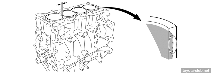
The cylinder block - aluminum "open deck" with thin cast iron liners. The liners are fused into block and their special rough outer surface promotes strong connection. The wall thickness between the cylinders 7 mm only, no overhaul with reboring provided by manufacturer.
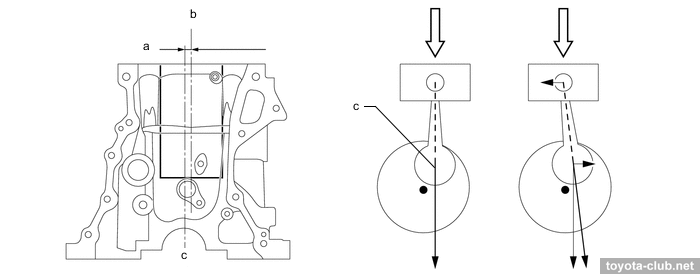
The axis of the crankshaft has been shifted by 8 mm relative to the cylinder axis lines (offset or "desaxage"), thus reducing the lateral component of the force exerted by the piston to the cylinder wall, reducing wear.
a - offset 8 mm, b - bore centerline, c - crankshaft centerline
|
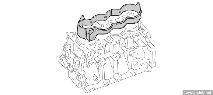
There is the spacer in the water jacket installed, it allows more intensive coolant circulation near the top of the cylinder, which improves heat dissipation and helps to more evenly thermally load.
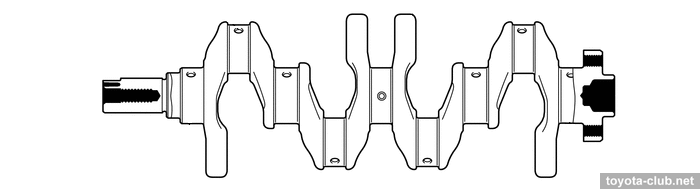
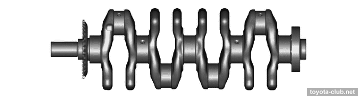
The crankshaft has 4 balance weights, narrowed journals and individual main bearing caps.
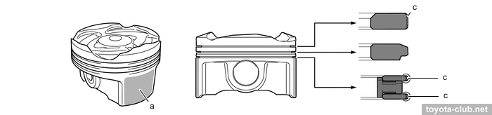
Pistons - alloy, compact T-shaped in projection, with cutted skirt. The groove for the upper compression ring is anodized, the edge of the upper compression ring and oil scraper have anti-wear PVD coating. A big drawback - piston pins are non full-floating, but press-fitted into the connecting rod. Note: for 1NR..2NR engines, Toyota officially prohibits the reuse of pistons, connecting rods and piston pins if they were disassembled.
a - resin coating, c - PVD coating
|
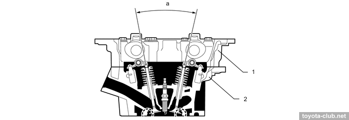
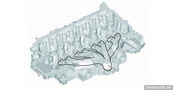
The camshafts are installed in a separate housing, which mounted on the cylinder head - it simplifies the design and manufacturing technology of cylinder head.
There are hydraulic lash adjusters and roller rockers in the valvetrain mechanism. "Indian" motors have old-style adjusting tappets.
1 - camshaft housing, 2 - cylinder head. a - 23.3°
|
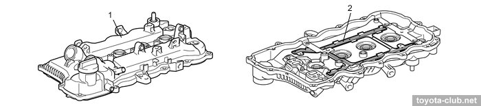
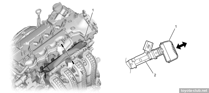
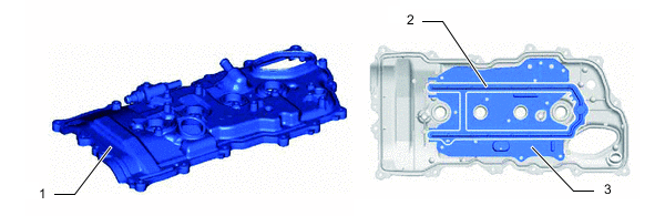
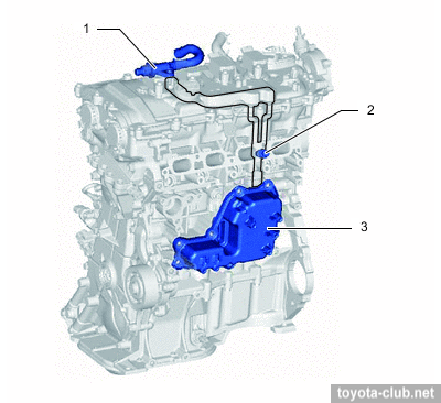
The head cover is made of plastic and provided with oil delivery pipe for the rockers lubrication.
1 - cylinder head cover, 2 - oil delivery pipe
|
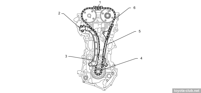
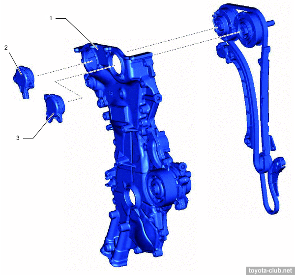
Timing drive - 16-valve DOHC, driven by single-row roller chain (pitch 8 mm) with hydraulic tensioner.
1 - chain vibration damper, 2 - chain tensioner, 3 - chain tension arm, 4 - crankshaft timing sprocket, 5 - timing chain guide, 6 - chain
|
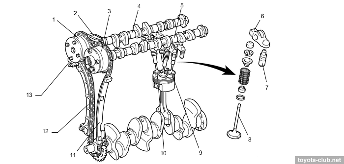
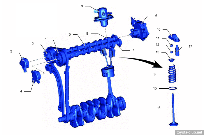
VVT actuators both on the inlet and outlet camshafts are installed (DVVT - Dual Variable Valve Timing). Timing variations range - 50° for intake and 45° for exhaust.
1 - VVT controller (intake), 2 - chain vibration damper, 3 - VVT controller (exhaust), 4 - intake camshaft, 5 - exhaust camshaft, 6 - valve rocker arm, 7 - valve lash adjuster, 8 - valve, 9 - exhaust valve, 10 - intake valve, 11 - timing chain guide, 12 - chain tension arm, 13 - chain tensioner
|
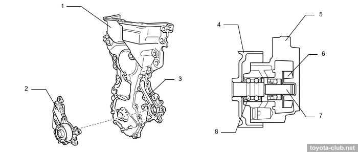
The water pump and oil pump are installed in cast timing chain cover.
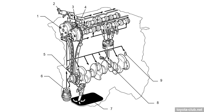
Lubrication
1 - VVT controller (intake), 2 - VVT control valve (intake), 3 - VVT controller (exhaust), 4 - VVT control valve (exhaust), 5 - oil pump, 6 - oil filter, 7 - oil strainer, 8 - oil nozzle, 9 - oil check valve
|
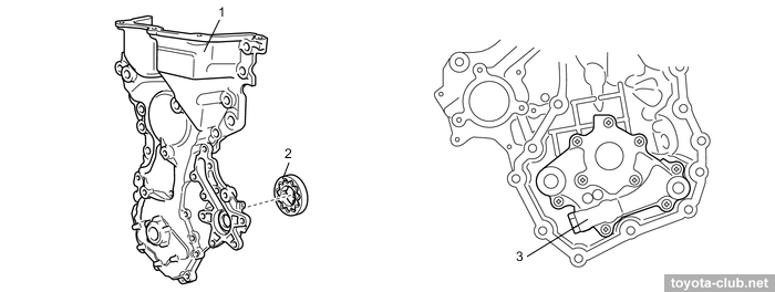
Trochoid oil pump is driven by crankshaft.
1 - chain cover, 2 - oil pump rotor, 3 - oil pump housing
|
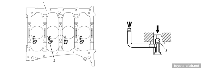
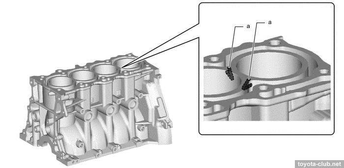
Oil nozzles that lubricate and cool the pistons are provided.
1 - cylinder block, 2 - oil nozzle, 3 - check ball
|
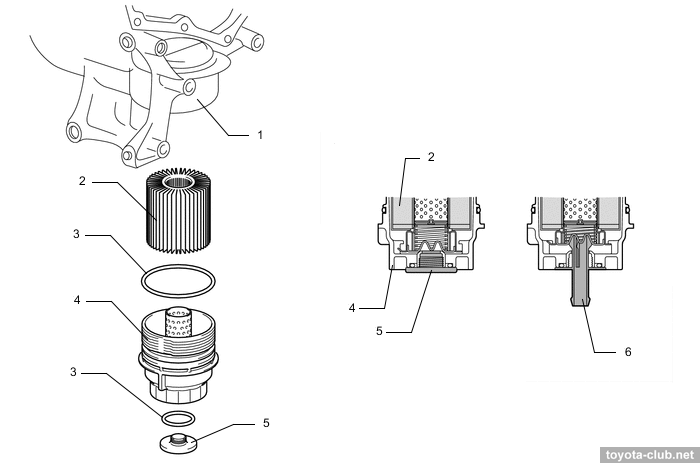
The oil filter is mounted vertically under the engine. The collapsible filter with replaceable cartridges are used.
1 - oil filter case, 2 - element, 3 - o-ring, 4 - filter cap, 5 - drain plug, 6 - drain pipe
|
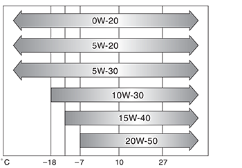
Officially prescribed oil viscosity for 1NR-FE:
Cooling
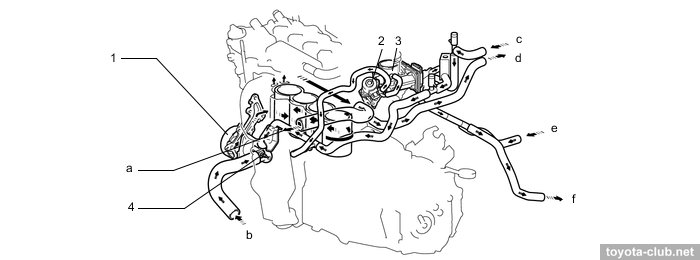
Cooling system is classic: pump drive by outer side of serpentine belt, "cold" (80-84°C) mechanical thermostat, heated throttle body.
1 - water pump, 2 - EGR valve, 3 - throttle body, 4 - thermostat. a - to radiator, b - from radiator, c - from heater radiator, d - to heater radiator, e - from exhaust heat recirculation system, f - to exhaust heat recirculation system
|
The coolant pump is mounted in the timing chain cover.
1 - chain cover, 2 - water pump, 3 - volute chamber, 4 - pump pulley, 5 - pump body, 6 - rotor, 7 - shaft, 8 - bearing
|
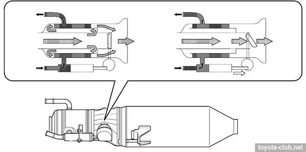
Versions for cold climate area are equipped with coolant heater (by exhaust gases). In the central pipe the valve actuator with the thermostat is integrated: after cold starting gases pass through the heat exchanger, then as the valve opens and the heating gases already flow to the exhaust.
Engine is equipped with separate fan motor control unit, which allows to adjust fan speed depending on the coolant temperature, refrigerant pressure, vehicle speed and engine speed.
Intake and exhaust
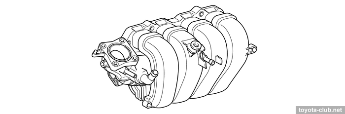
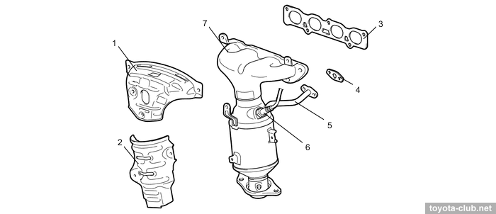
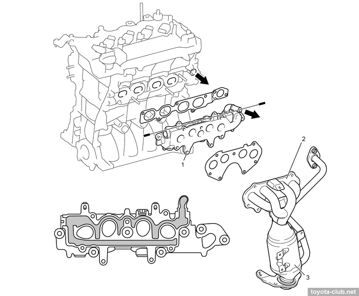
Plastic intake manifold mounted at bulkhead side, steel exhaust manifold - at front side.
1,2 - heat insulator, 3,4 - gasket, 5 - EGR pipe, 6 - air fuel ratio sensor, 7 - exhaust manifold converter
|
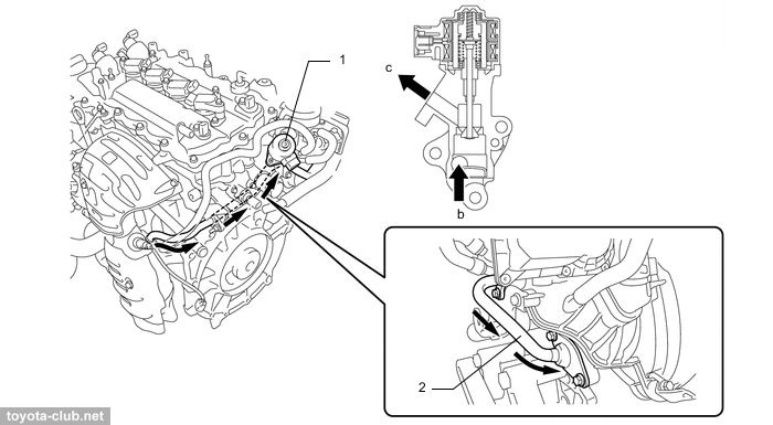
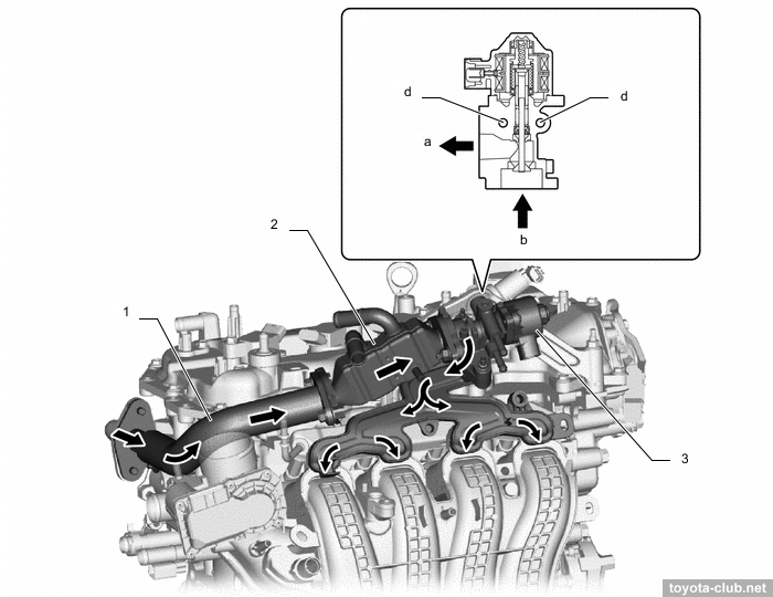
A great drawback - EGR system, with valve driven by stepper motor.
1 - EGR valve, 2 - EGR pipe. b - from cylinder head, c - to intake manifold
|
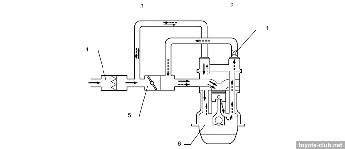
PCV system. 1 - ventilation valve, 2 - ventilation hose, 3 - ventilation hose 2, 4 - air cleaner case, 5 - throttle body, 6 - crankcase.
|
Control system
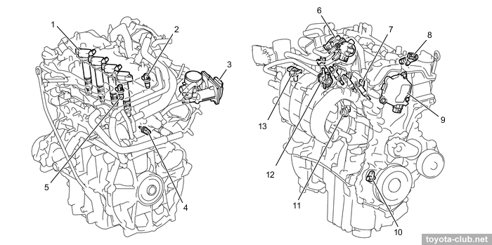
1 - VVT control valve (intake), 2 - VVT control valve (exhaust), 3 - ignition coil, 4 - camshaft position sensor (exhaust), 5 - air fuel ratio sensor, 6 - crankshaft position sensor, 7 - coolant temperature sensor, 8 - knock sensor, 9 - EGR valve, 10 - throttle body, 11 - fuel injector, 12 - camshaft position sensor (intake), 13 - vacuum sensor
|
Fuel injection - traditional multipoint, sequential under normal conditions, at low temperature and low speed grouped injection can be performed.
- Mass air flow sensor (MAF) - "hot wire" type, combined with the intake temperature sensor..
- Manifold pressure sensor (MAP) was installed in Euro 5 modifications..
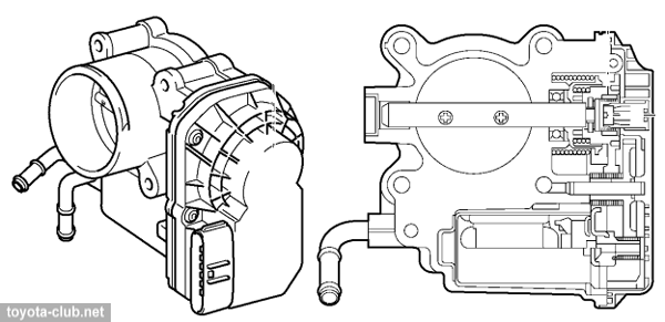
- Throttle valve - fully electronically controlled (ETCS): DC motor, dual-channel non-contact position sensor (Hall effect) ETCS performs some functions of traction control (TRC) and stabilization (VSC).
- Accelerator pedal position sensor - dual-channel non-contact (Hall effect)..
- Crankshaft and camshaft position sensors - MRE type (magnetoresistive), provide a digital output signal and work properly at low engine speed.
- Knock sensor - wideband "flat" piezoelectric, unlike the old type of resonant knock sensors it feels a wider range of vibration frequencies.
- Upstream catalyst - planar type air-fuel ratio (AFS) sensor (advantage - rapid heating), downstream - normal oxygen sensor.
- Injectors with elongate nozzle are installed in the cylinder head and the fuel is injected as close as possible to the intake valves..
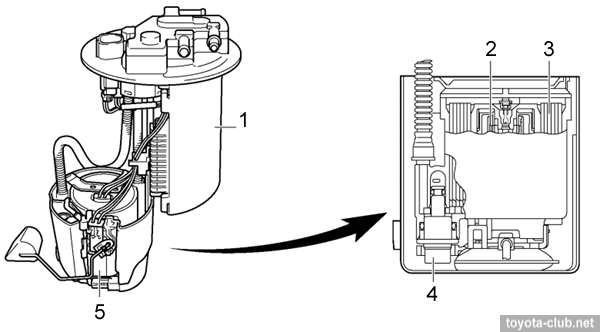
- Fuel supply - without return line. In addition to the pressure regulator and level gauge sensor, EVAP canister is combined with the fuel pump in the tank.
1 - canister, 2 - fuel pump, 3 - fuel filter, 4 - pressure regulator, 5 - fuel level gauge sensor.
|
Electrical
Ignition system - DIS-4 (separate coil for each cylinder). Spark plugs - thin "iridium" SG20HR11 with long threaded portion, hex 14 mm.
There are a few new features in starting system. Semi-automatic starting - it is enough to turn the key to START and release, after which the control system automatically keeps the starter on until the engine start. When the stop-start system is active, the control remembers cycle phase for each cylinder after engine stall, so at re-start the fuel and spark are supplied the cylinder which is able to join in the work immediately.
Charging system - with segment conductor alternators, 80-100A output, one-way clutch in pulley.
Continuously charging of battery is carried out during deceleration, but in steady-state mode cycles of charging and discharging of the battery are alternates for maximum efficiency. More complex control system required to use the battery temperature sensor and current sensor..
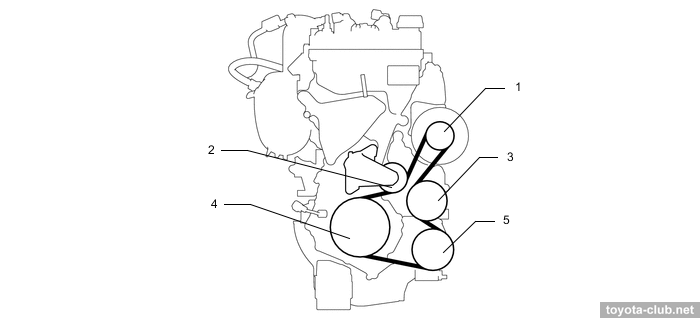
Auxiliary drive - by single serpentine belt with automatic tensioner.
1 - generator pulley, 2 - belt tensioner, 3 - water pump pulley, 4 - crankshaft pulley, 5 - compressor pulley
|
| 1NR-FKE (1.3 EFI DVVT-iE) / 2NR-FKE (1.5 EFI DVVT-iE) |
Among the differences from the basic 1NR-FE noting::
• Variable valve timing system VVT-iE - electrical controller for intake and traditional hydraulic VVT controller for exhaust - see "Toyota Variable Valve Timing. VVT-iE (gen.II)".
1 - VVT-iE timing gear, 2 - VVT controller (exhaust), 3 - intake camshaft, 4 - exhaust camshaft
|
• Implemented a possibility of engine operation by Miller / Atkinson cycle - see details.
• High geometric compression ratio.
• Additional cooling channels in the cylinder block.
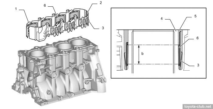
• Complex spacer in the water jacket..
1 - spacer 1, 2 - spacer 2, 3 - spring, 4 - cylinder bore, 5 - water jacket, 6 - foam rubber
|
• Crankshaft with 8 counterweights.
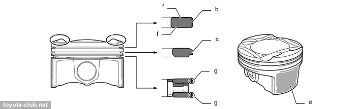
• Pistons and rings with a wide variety of coatings.
b - DLC coating (Diamond Like Carbon), c - chrome plating, e - resin coating, f - nitride treatment, g - DLC coating
|
• Updated topology of the cooling system.
1 - water pump, 2 - water inlet with thermostat, 3 - throttle body, 4 - transmission oil cooler, 5 - EGR cooler, 6 - EGR valve. a - to radiator, b - from radiator, c - from heater radiator, d - to heater radiator
|
• Updated topology of the lubrication system.
1 - VVT controller (exhaust), 2 - VVT control valve (exhaust), 3 - oil delivery pipe, 4 - valve lash adjuster, 5 - oil nozzle, 6 - oil filter, 7 - oil pump
|
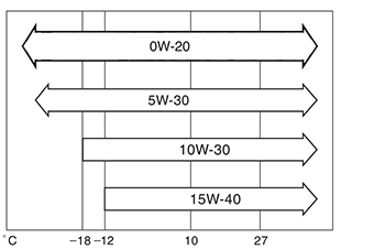
Officially prescribed oil viscosity for 2NR-FKE:
• Exhaust gas cooler is installed between the exhaust manifold and the cylinder head (to protect the catalyst).
1 - exhaust cooler, 2 - exhaust manifold converter, 3 - catalyst
|
• A whole EGR module has been installed, that includes control valve, cooler and a gas dispenser that uniformly feeds them into the channels of the intake manifold.
1 - EGR pipe, 2 - EGR cooler, 3 - EGR valve. a - to intake manifold, b - from exhaust manifold, d - water passage
|
• New components of the control system.
1 - ignition coil, 2 - camshaft position sensor (intake), 3 - throttle body, 4 - coolant temperature sensor, 5 - camshaft position sensor (exhaust), 6 - EGR valve, 7 - fuel injector, 8 - VVT control valve (exhaust), 9 - VVT-iE controller (intake), 10 - crankshaft position sensor, 11 - knock sensor, 12 - VSV, 13 - vacuum sensor
|
• Fuel delivery pipe - steel-stamped; its walls themselves serve as a damper for fuel pressure pulsations.
1 - fuel delivery pipe, 2 - fuel injector
|
Note fundamental aspects and differences of the motor, that not like the other engines of the series.
Engine mechanical
- Variable valve timing system VVT-iW - see details.
- Implemented a possibility of engine operation in Miller / Atkinson cycle - see details.
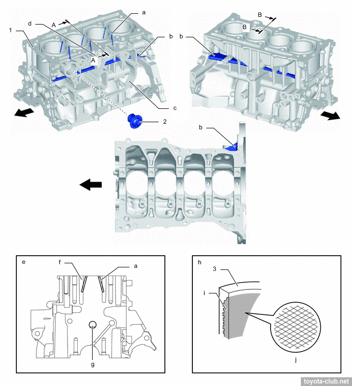
- Strengthening cylinder block.
1 - cylinder block, 2 - thermostat (block), 3 - cylinder bore. a - water passage, b - rib, c - oil separate chamber 1, d - knock sensor boss, f - water jacket, g - breather hole, i - liner, j - bore honing.
|
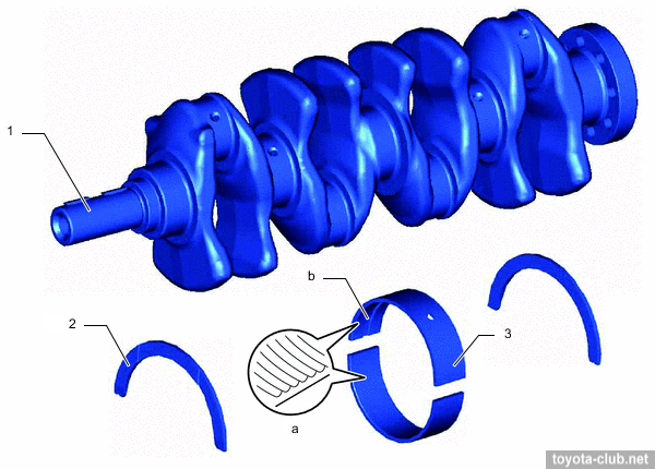
- Crankshaft with 8 counterweights.
1 - crankshaft, 2 - thrust washer, 3 - bearing. a - micro-grooved, b - oil groove.
|
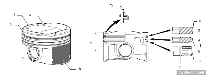
1 - piston, 2 - anti-friction ring carrier, 3 - upper compression ring, 4 - lower compression ring, 5 - oil ring, 6 - expander. a - combustion chamber, b - polymer coating, c - compression height, e - PVD coating, f - chrome coating.
|
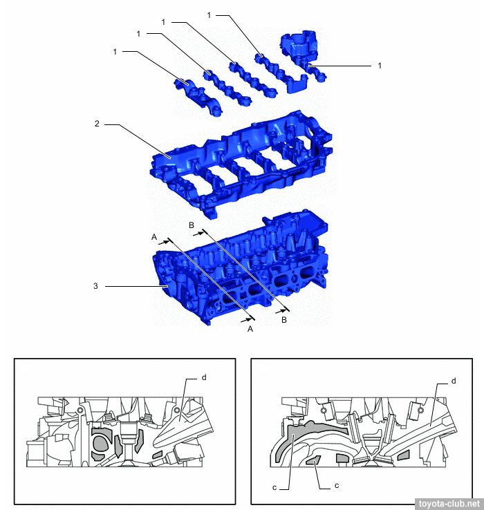
1 - camshaft bearing cap, 2 - camshaft housing, 3 - cylinder head. c - water jacket (2-stage), d - intake port.
|
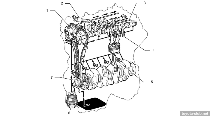
- Supply pump driven by additional cam of the intake camshaft.
- Vacuum pump driven by the exhaust camshaft (for brake booster operation and turbocharger control).
1 - timing chain cover, 2 - VVT-i solenoid, 3 - VVT-iW solenoid.
|
1 - intake camshaft sprocket, 2 - exhaust camshaft sprocket, 3 - VVT-i solenoid, 4 - VVT-iW solenoid, 5 - exhaust camshaft, 6 - vacuum pump, 7 - intake camshaft, 8 - fuel pump driving cam, 9 - high pressure fuel pump, 10 - valve rocker, 11 - valve stem cap, 12 - valve spring retainer lock, 13 - valve spring retainer, 14 - valve spring, 15 - valve spring seat, 16 - valve, 17 - lash adjuster.
|
- Cylinder head cover made of aluminium.
1 - cylinder head cover, 2 - oil delivery pipe, 3 - baffle plate.
|
- Applied sodium cooled valves.
- The exhaust manifold is integrated into the cylinder head.
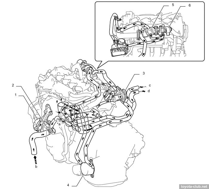
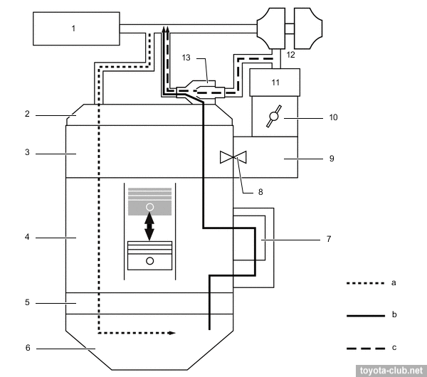
• Crankcase ventilation system.
The boost means as increasing the amount of crankcase bypass gases and inability to utilize it by conventional method using the intake vacuum. Therefore, the ejector is mounted in the head cover, so in boost mode gases with high content of hydrocarbons do not fall into the atmosphere but return to the intake and then burn in the cylinder.
Another separator chamber is installed to crankcase.
1 - ejector, 2 - PCV valve, 3 - oil separate chamber.
|
In the boost mode crankcase gases discharged via the ejector to intake.
1 - air cleaner, 2 - cylinder head cover, 3 - cylinder head, 4 - cylinder block, 5 - crankcase, 6 - oil pan, 7 - oil separate chamber, 8 - PCV valve, 9 - intake manifold, 10 - throttle body, 11 - intercooler, 12 - turbocharger, 13 - ejector. a - fresh air, b - fresh air + blowby gas, c - ejector drive gas.
|
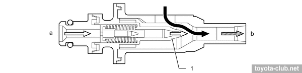
The ejector operates on the principle of Venturi - crankcase gases are sucked into the stream of flowing compressed air.
1 - nozzle. a - air from downstream of turbocharger, b - to upstream of turbocharger.
|
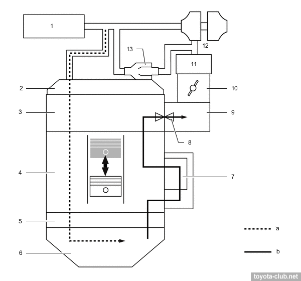
Without a significant boost, crankcase gases are sucked through a conventional PCV valve.
1 - air cleaner, 2 - cylinder head cover, 3 - cylinder head, 4 - cylinder block, 5 - crankcase, 6 - oil pan, 7 - oil separate chamber, 8 - PCV valve, 9 - intake manifold, 10 - throttle body, 11 - intercooler, 12 - turbocharger, 13 - ejector. a - fresh air, b - fresh air + blowby gas.
|
Cooling system
• The engine is equipped by two thermostats:
- Traditional thermostat (opening temperature 80-84°C) in the water inlet controls the coolant flow through the radiator
- Thermostat on the cylinder block (opening temperature 76-80°C) controls the coolant flow through the block, to maximal fast warming up
1 - cylinder head, 2 - water inlet, 3 - thermostat (block), 4 - cylinder block, 5 - water pump, 6 - throttle body, 7 - thermostat, 8 - intercooler reserve tank, 9 - radiator, 10 - bleeder valve, 11 - heater radiator, 12 - CVT fluid warmer.
|
• Built-in cylinder head exhaust manifold allows to cool the exhaust gases before its entering to the turbocharger.
Lubrication
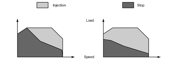
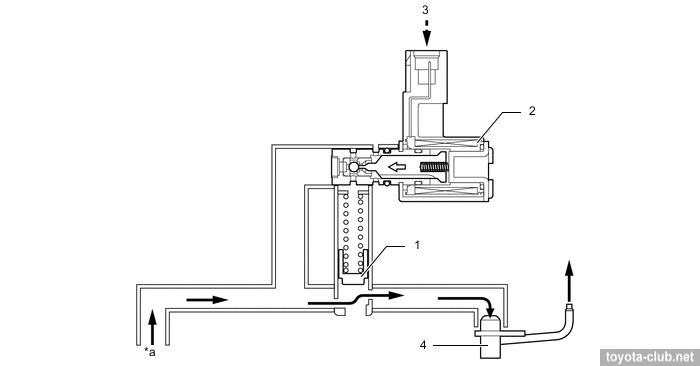
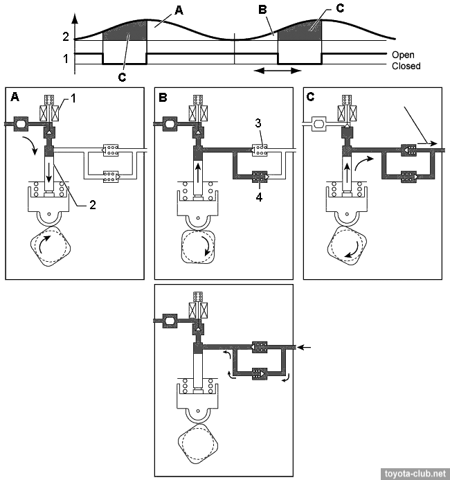
• Unlike other engines with common nozzles for piston lubrication and cooling, the ECM can control the oil injection depending on external conditions.
Cold engine / Warmed up engine
|
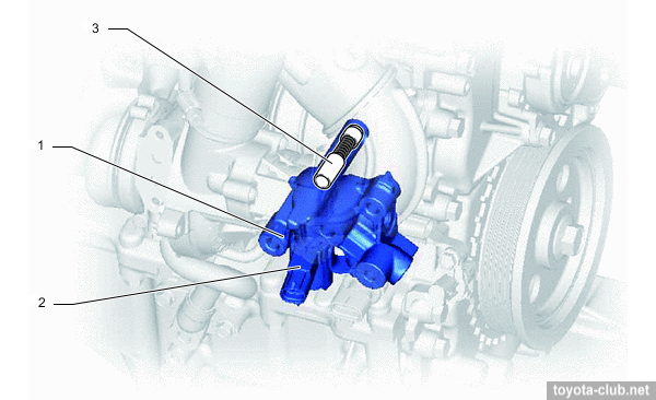
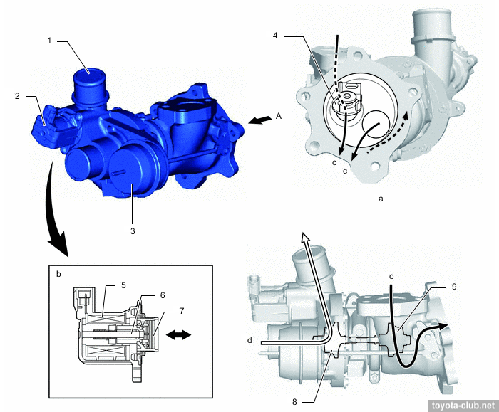
Relief and control valves are installed in oil pump relief valve housing.
1 - oil pump relief valve housing, 2 - oil pressure switching valve, 3 - relief valve.
|
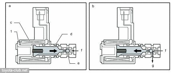
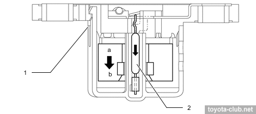
1 - oil pressure switching valve. a - closed, b - opened, c - coil, d - plunger, e - ball, f - from oil pump, g - to relief valve.
|
1) The oil supplied to the rear of the relief valve, cutting off the oil flow to the nozzles.
1 - relief valve, 2 - oil control valve, 3 - ECM, 4 - nozzle. a - engine oil.
|
2) The oil flow to relief valve end stops, the valve opens and the oil is supplied to the nozzles.
1 - relief valve, 2 - oil control valve, 3 - ECM, 4 - nozzle. a - engine oil, b - drain.
|
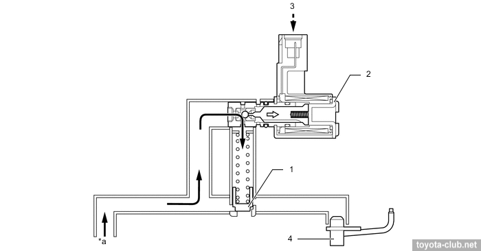
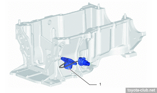
• Engine oil level sensor is installed.
1 - oil level sensor, 2 - oil level switch. a - ON, b - OFF.
|
Intake and exhaust
1 - turbocharger, 2 - air bypass valve, 3 - actuator, 4 - wastegate valve, 5 - coil, 6 - shaft, 7 - valve, 8 - compressor wheel, 9 - turbine wheel. c - exhaust gas, d - intake air.
|
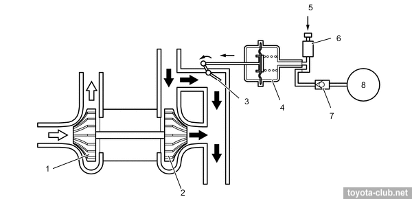
Boost pressure control is performed by classic wastegate valve.
- When the engine is stopped - WGT valve open.
- When starting control valve shuts off the vacuum supply from the pump to the actuator, which in turn opens WGT. As a result, the hot exhaust gases flow directly into the converter to accelerate its warm-up.
- At low loads, when there is no need for a boost, opened WGT reduces resistance and reduces pumping losses at exhaust. By reducing the amount of residual gas the stability of the combustion process is increased.
1 - compressor wheel, 2 - turbine wheel, 3 - wastegate valve, 4 - actuator, 5 - ECM, 6 - vacuum regulating valve, 7 - check valve 2, 8 - vacuum pump.
|
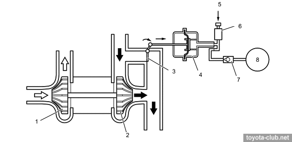
- At high load WGT is closed and the turbine comes into effective operation.
1 - compressor wheel, 2 - turbine wheel, 3 - wastegate valve, 4 - actuator, 5 - ECM, 6 - vacuum regulating valve, 7 - check valve 2, 8 - vacuum pump.
|
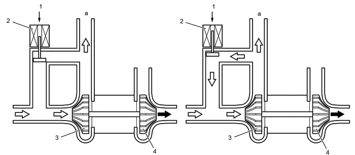
Air bypass valve serves to prevent a situation where the sudden closing of the throttle rouse to pressure incresing between the turbocharger and the throttle, until the occurrence of reverse flow, accompanied by abnormal noise.
1 - ECM, 2 - air bypass valve, 3 - compressor wheel, 4 - turbine wheel. a - to throttle body.
|
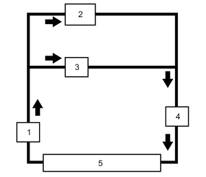
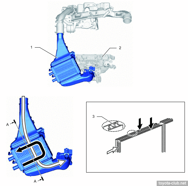
• Independent turbocharger cooling circuit with an electric pump and own radiator is used.
1 - electric water pump, 2 - intercooler, 3 - turbocharger, 4 - intercooler reserve tank, 5 - intercooler radiator.
|
- Intercooler - water-air type.
1 - intercooler, 2 - intake manifold, 3 - inner fin.
|
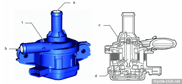
- ECM controls the coolant flow rate and cooling efficiency by electric pump speed.
Electric pump. a - inlet, b - outlet, c - rotor, d - shaft.
|
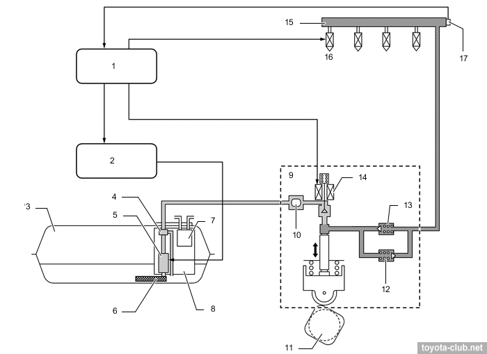
Fuel injection system (D-4T)
1 - ECM, 2 - fuel pump control unit, 3 - fuel tank, 4 - fuel pressure regulator, 5 - fuel pump (low pressure), 6 - fuel pump filter, 7 - charcoal canister, 8 - fuel suction tube, 9 - fuel pump (high pressure), 10 - fuel pressure pulsation damper, 11 - camshaft, 12 - relief valve, 13 - check valve, 14 - control valve, 15 - fuel rail, 16 - injector, 17 - fuel pressure sensor.
|
Fuel injection - direct in the combustion chamber, is synchronized with piston position. The fuel from tank pump is supplied to high pressure pump, than under pressure into the fuel rail, and finally into the cylinders by injectors. Injection can be carried out several times at the cycle.
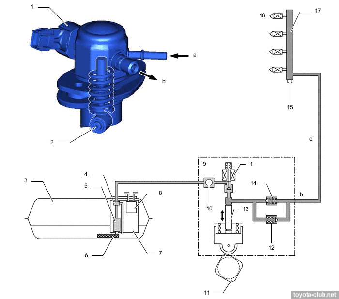
Injection/supply pump. Single-plunger with control valve, relief valve, check valve and pulsation damper at inlet. Mounted on the valve cover and dreven by 4-lobes cam of the camshaft. The fuel pressure is regulated in the range 2.4-20 MPa depending on driving conditions.
1 - control valve, 2 - roller lifter, 3 - fuel tank, 4 - fuel pressure regulator, 5 - fuel pump (low pressure), 6 - fuel suction filter, 7 - fuel suction tube, 8 - charcoal canister, 9 - fuel pump (high pressure), 10 - fuel pressure pulsation damper, 11 - camshaft, 12 - relief valve, 13 - plunger, 14 - check valve, 15 - fuel pressure sensor, 16 - injector, 17 - fuel rail. a - low-pressure, b - high-pressure, c - high-pressure pipe.
|
- At inlet stroke (A) the plunger 2 moves downward and fuel draws into the pumping chamber.
- At the beginning of the compression stroke (B) part of the fuel is returned while control valve 1 is open (the specified fuel pressure is set).
- At the end of the compression stroke (C) the control valve is closed and the pressurized fuel through the check valve 3 is supplied into the fuel rail.
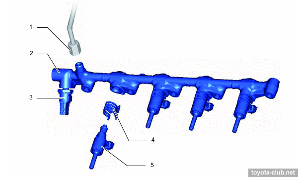
Fuel rail. Made of forged iron, contains fuel pressure sensor to provide feedback.
1 - fuel pipe (high pressure), 2 - fuel rail, 3 - fuel pressure sensor, 4 - injector holder, 5 - injector.
|
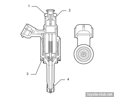
Injectors. Slotted nozzle injector injects the fuel into the cylinder as specific shaped spray that draws in a significant amount of air and increases the mass admission. Sealing teflon (PTFE) rings further reduce vibration.
1 - O-ring, 2 - backup ring, 3 - insulator, 4 - teflon seal.
|
Spark plugs. - NGK DILKAR8J9G, gap 0.8-0.9 mm.
To date, a comprehensive statistics on the operation of 1NR-FE engines have been accumulated (contrary to expectations, it's not so negative), while the -FKE and -FTS engines that appeared later are still at the stage of experience accumulating.
• The most famous and mass problem of 1NR-FE - is excessive oil consumption, which often appears at mileage substantially below 100 thousand kilometers. The reason is traditional for Toyota - the piston rings stuck. The need to replace pistons together with the conrods does not allow to renew the engine cheaply, but at least the cylinder block reboring is not an obligatory option.
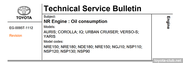
The problem of oil consumption was recognized and described in TSB EG-0095T-1112, some production changes were implemented in early 2013. In addition to modified rings and pistons (with conrods), the valve cover and oil nozzles may have to be replaced.
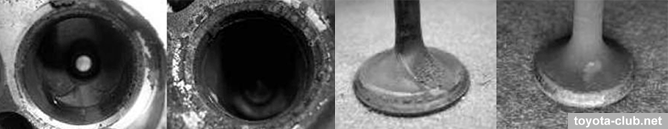
• Excessive deposits of soot in the combustion chamber, on the valves and valve seats, lead to compression decrease, that causes elongated engine start (more than three seconds), which also generates DTC P1604. The defect is recognized and described in TSB EG-00037T-TME. Prescriptions are not so - install a new battery and a modified starter.
• Similar bulletin TSB EG-0091T-1112 - excessive carbon deposits on valves and seats, resulting in difficult starting, rough idle, stalling engine and DTC P1603..1605. Prescriptions - replacement of pistons, rings and connecting rods and cleaning the cylinder head from carbon deposits.
• A ticking or clattering noise from the timing chain area, more noticeable after a cold start till warming up. Recognized as "feature" and described in TSB EG-00039T-TME. Prescriptions - either do nothing, or replace the timing chain with a new one and install a modified tensioner arm.
• Rattle or knocking noise during engine operation, again due to excessive deposits in the combustion chamber. The defect is recognized and described in TSB EG-0094T-0714, some production changes implemented at the beginning of 2014. The prescriptions are almost identical to the EG-0095T-1112 - but it is recommended to replace the pistons with the next, even more modified version, and reprogram the engine ECU firmware.
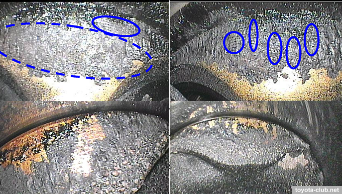
• The MIL lights on with DTC P2111 or P2112. The defect is recognized and described in TSB EG-0027T-0313, some production changes implemented at the end of 2012. The prescription is to replace the throttle body assembly and update the ECU firmware.
• For 8NR-FTS engine just list a few TSBs that contain recognized defects:
·EG-00014T-TME "8NR-FTS Turbo Overboost DTC P023400"
·EG-00105T-TME "Rattle noise from exhaust (front) due to broken heat insulator bracket"
·EG-00113T-TME "8NR-FTS Noise from the vacuum regulating valve"
·EG-00219T-TME "8NR-FTS Engine Coolant Flow Noise"
·EG-00094T-TME "8NR-FTS Cylinder Misfire DTC P030100, P030200, P030300, P030400, P030027, P030085" (ignition coils replacement is prescribed)
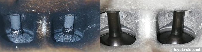
If the measures taken are ineffective, it is recommended to clean the intake valves from carbon deposits.
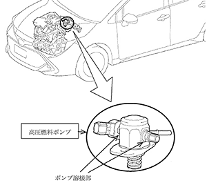
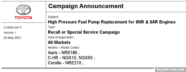
• Recall #4961 (27.05.2021) for 2019-2021 JDM vehicles with 8NR-FTS engine (Corolla, C-HR). The welded part of the high-pressure fuel pump may be cracked due to low resistance against the pressure which cause fuel leakage. Prescription - replace the HP fuel pump.
The corresponding campaign (21SMD-041T, 05/26/2021) has also been launched globally.
• And once again - for the health and longevity of Toyota engines (and NR in particular), it is just necessary to deactivate EGR system - some owners just reprogram the software, but plugging the gas channel with a metal plate seems to be a more reliable solution.
|
Toyota engines review
·
AZ ·
MZ ·
NZ ·
SZ ·
ZZ ·
AR ·
GR ·
KR ·
NR ·
ZR ·
AD ·
GD ·
ND ·
VD ·
A25.M20 ·
F33 ·
G16 ·
M15 ·
V35 ·
|
|
|